Process for producing golf ball

a golf ball and production process technology, applied in the field of golf ball production process, can solve the problems of deterioration of working property, increase of production cost of golf ball, and process yield reduction, and achieve the effect of remarkable

Inactive Publication Date: 2005-01-25
SUMITOMO RUBBER IND LTD
View PDF10 Cites 13 Cited by
  • Summary
  • Abstract
  • Description
  • Claims
  • Application Information

AI Technical Summary

Benefits of technology

The process for producing a golf ball according to the present invention exerts especially remarkable effects when the rubber composition is placed into the cavity with the spherical center in a state where the rubber composition is positioned surrounding this center.

Problems solved by technology

However, the outflow of a large amount of rubber composition leads directly to a decreased process yield, thereby elevating the cost of producing a golf ball.
Accordingly, working property is deteriorated in removing the molding flash.
In addition, varying amount of the outflow also leads to deviation of mass of the mid layer (uneven wall thickness).
Problems involving a deteriorated working property when removing the molding flash are also raised upon the compression molding of one-piece golf balls and the cores for a two-piece golf ball, the centers for a multi-piece golf ball, and the like.

Method used


Image

  • Process for producing golf ball
  • Process for producing golf ball
  • Process for producing golf ball

Examples


example 1

A rubber composition was obtained by kneading 100 parts of polybutadiene (“BR01”, trade name by JSR Corporation), 25 parts of zinc acrylate, 22 parts of zinc oxide and 1.0 part of dicumyl peroxide in an internal kneading machine. This rubber composition was placed in a mold having a spherical cavity, kept at 142° C. for 23 minutes and further kept at 168° C. for 6 minutes to obtain a center having a diameter of 30.2 mm.

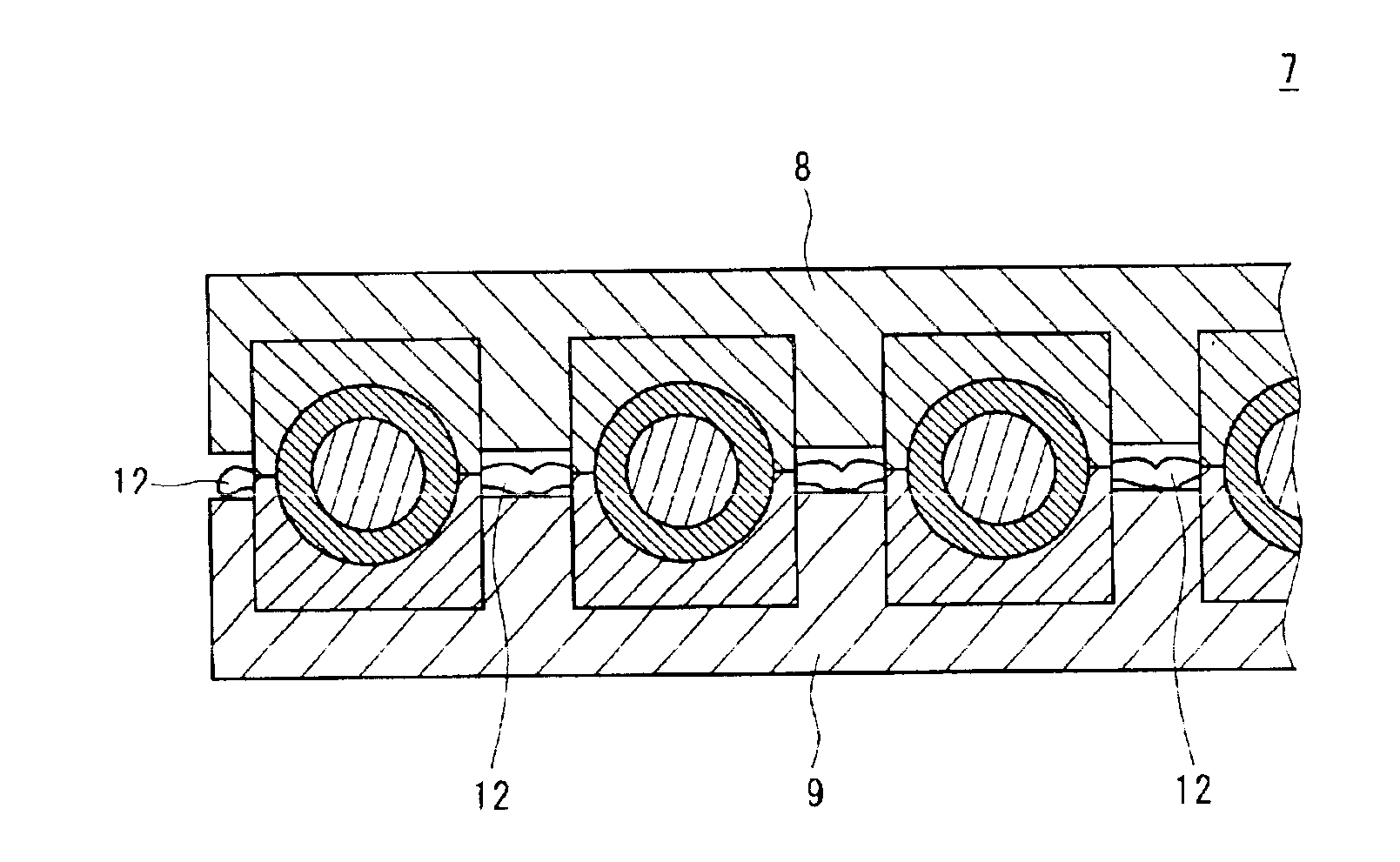
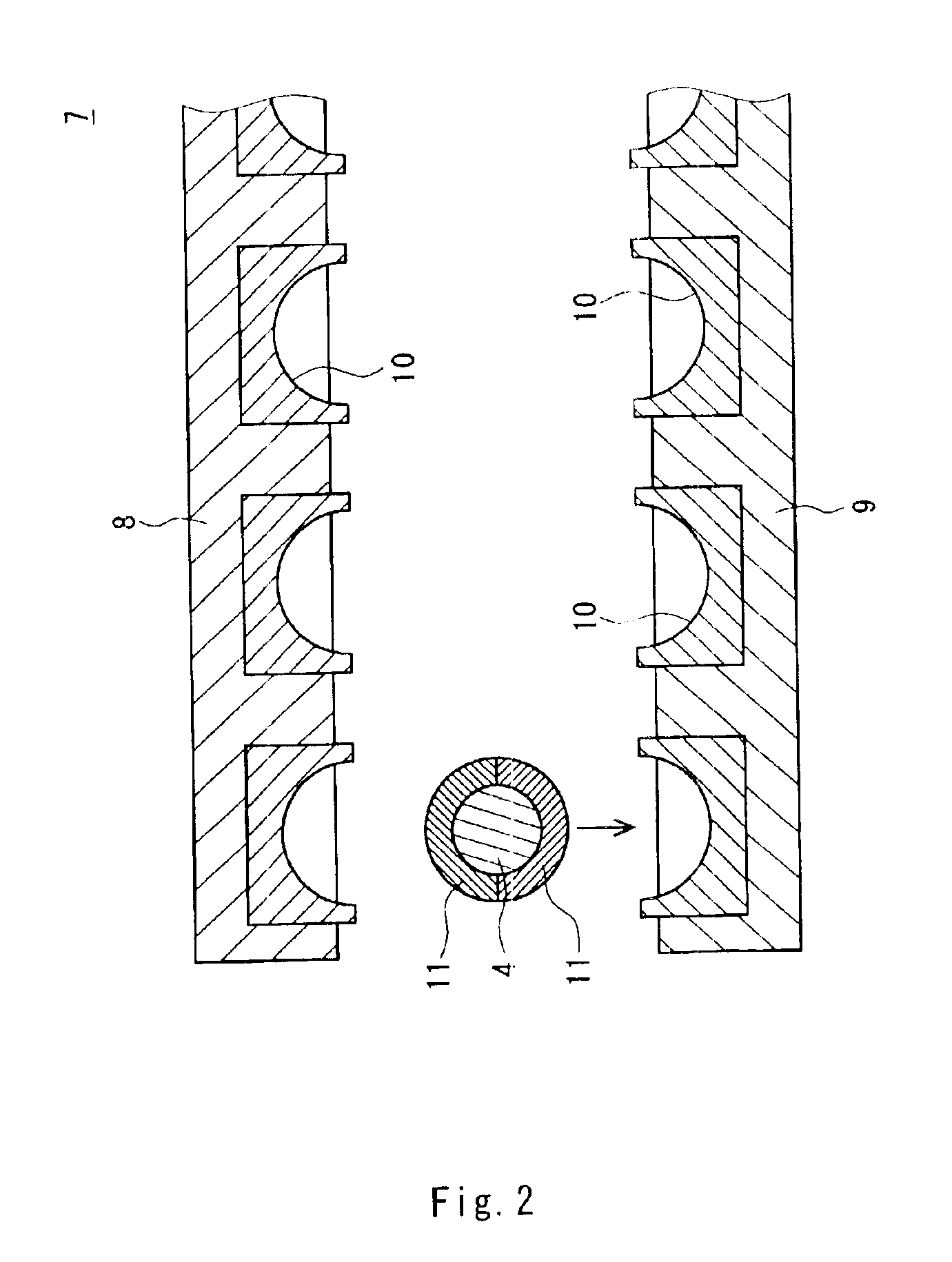
Next, a rubber composition was obtained by kneading 80 parts of polybutadiene (“BR01”, trade name, supra), 20 parts of another polybutadiene (“BR10”, trade name, supra), 34 parts of zinc acrylate, 16.3 parts of zinc oxide and 1.0 part of dicumyl peroxide in an internal kneading machine. This rubber composition was placed into a mold and compressed to give a half shell. The center was covered with two of the half shells, and the center and the half shells were placed into a mold shown in FIG. 2. Thereafter, the lower portion was moved upwards at a moving velocity of 10...

examples 6 to 10

In a similar manner to Example 1 except that the space between the upper and lower portions upon initiation of the clamping step was altered as represented in Table 2 below, a core was formed.

example 11

In a similar manner to Example 1 except that the upper portion and the lower portion were brought into contact by moving the lower portion upwards at a moving velocity of 1.0 mm / s, from a state where the mold is unclamped utmost, a core was formed.

Evaluation of Working Property

Facility in removing operation of the molding flash was evaluated by an operator. A case where the molding flash was extremely ready to be removed, it was evaluated as “A”; a case where the molding flash was rather difficult to be removed, it was evaluated as ‘B’; and a case where the molding flash was difficult to be removed and thus long time period is required for the operation was evaluated as “C”. The results of evaluation are shown in Table 1 and Table 2 below.

Evaluation of Mass Deviation

Four positions for the measuring point equally spaced were selected along a seam on the surface of the mid layer, and further, additional positions for the measuring point were also selected which corresponded to bipolar...


PUM

PropertyMeasurementUnit
moving velocityaaaaaaaaaa

Abstract

A process for producing a golf ball which includes the steps of placing a rubber composition into the cavity of a mold having an upper portion and a lower portion, clamping the upper portion and the lower portion together at a moving velocity of from 0.03. mm/s to 1.0 mm/s, causing excess rubber composition to flow out from the cavities; and unclamping the mold and removing from the mold cavity spherical bodies and associated rubber flashers formed in the mold cavities.

Description

BACKGROUND OF THE INVENTIONThis nonprovisional application claims priority under 35 U.S.C. § 119(a) on Patent Application No. 2001-316148 filed in JAPAN on Oct. 15, 2001, which is herein incorporated by reference.1. Field of the InventionThe present invention relates to a process for producing a golf ball. More particularly, the present invention relates to an improvement in the compression molding processes of a golf ball or a spherical body that forms a part of a golf ball.2. Description of the Related ArtThere exist solid golf balls having a variety of layered structures. For example, there are one-piece golf balls including a single layer, two-piece golf balls including a cover and a core having a single-layered structure, and multi-piece golf balls including a cover and a core having a two-layered structure. The core has a two-layered structure including a center and a mid layer covering over the center. Any of the one-piece golf balls, the cores for a two-piece golf ball, and ...

Claims


Application Information

Patent Timeline
Patent Type & Authority Patents(United States)
IPC IPC(8): B29C43/36B29C43/20B29C33/00B29C37/00B29C37/02B29C43/02A63B45/00B29C45/56B29K21/00B29L31/52
CPCB29C43/20B29C43/36B29C33/0022B29C33/0055B29C37/02B29C43/021Y10S425/812B29C43/52B29K2021/00B29L2031/54B29L2031/545B29L2031/772
Inventor SUGIMOTO, KAZUSHIGE
Owner SUMITOMO RUBBER IND LTD
Why Eureka
Try Eureka