
Light-emitting device, display panel and fabrication method of light-emitting device

An electroluminescent device and light-emitting layer technology, which is applied in the fields of electro-solid devices, semiconductor/solid-state device manufacturing, electrical components, etc., can solve the problem of inability to effectively improve device extraction efficiency and adjust color gamut, weak microcavity effect, and light emissivity. Low problems, to achieve the effect of improving the front light output efficiency, simple production method and adjusting color gamut

Active Publication Date: 2018-08-03
GUANGDONG JUHUA PRINTING DISPLAY TECH CO LTD
View PDF8 Cites 9 Cited by
  • Summary
  • Abstract
  • Description
  • Claims
  • Application Information

AI Technical Summary

Problems solved by technology

Transparent electrodes have good light transmittance, low light emissivity, and weak microcavity effect, which cannot effectively improve the front light extraction efficiency of the device and adjust the color gamut

Method used

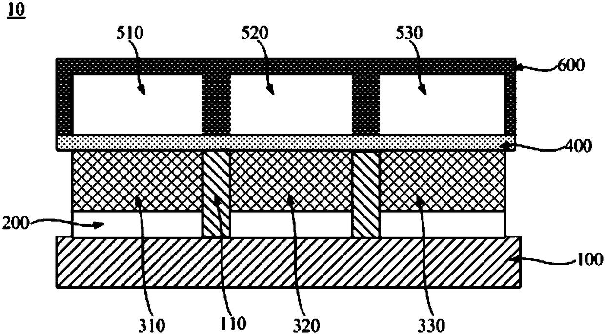
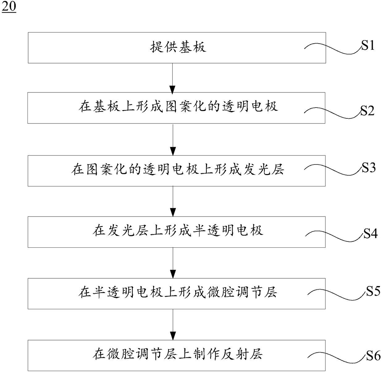
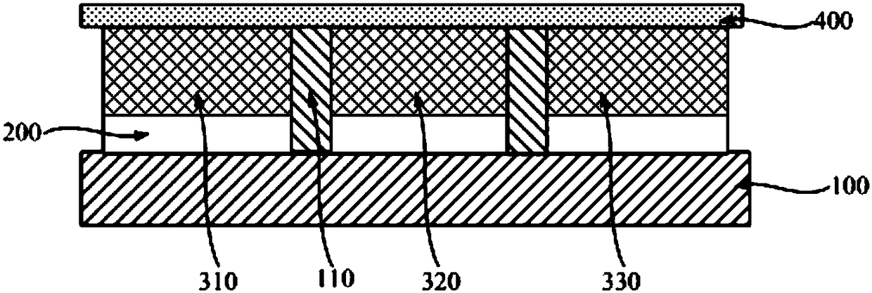

Image

  • Light-emitting device, display panel and fabrication method of light-emitting device
  • Light-emitting device, display panel and fabrication method of light-emitting device
  • Light-emitting device, display panel and fabrication method of light-emitting device

Examples


Embodiment Construction

[0034] In order to facilitate the understanding of the present invention, the present invention will be described more fully below with reference to the associated drawings. Preferred embodiments of the invention are shown in the accompanying drawings. However, the present invention can be embodied in many different forms and is not limited to the embodiments described herein. On the contrary, these embodiments are provided to make the understanding of the disclosure of the present invention more thorough and comprehensive.

[0035] It should be noted that when an element is considered to be "connected" to another element, it may be directly connected to the other element or there may be intervening elements at the same time.

[0036] Unless otherwise defined, all technical and scientific terms used herein have the same meaning as commonly understood by one of ordinary skill in the technical field of the invention. The terms used herein in the description of the present inve...


PUM


Abstract

The invention relates to a light-emitting device, a display panel and a fabrication method of the light-emitting device. The light-emitting device comprises a transparent electrode, a light-emitting layer, a half-transparent electrode, a micro-cavity adjustment layer and a reflection layer which are sequentially arranged on a substrate, wherein the half-transparent electrode, the micro-cavity adjustment layer and the reflection layer form a micro-cavity adjustment structure. Compared with an existing bottom emission light-emitting device, the light-emitting device has the advantages that the front-surface light giving-out efficiency of the light-emitting device can be effectively improved, and the color domain can be adjusted; and meanwhile, the micro-cavity adjustment structure of the light-emitting device is formed at an outer side of the electrode of the light-emitting device, and no influence on charge transmission and recombination of the light-emitting device during working is generated, and the light-emitting device is simpler and more effective.

Description

technical field [0001] The invention relates to the field of displays, in particular to an electroluminescent device, a display panel and a manufacturing method thereof. Background technique [0002] Organic light-emitting diodes (OLEDs) have become the main development direction of next-generation display technology due to their advantages such as self-luminescence, fast response, wide viewing angle, high brightness, thinness and flexibility. [0003] The quantum efficiency of existing electroluminescent devices such as OLEDs has almost reached 100%, but only about 20% of the photons can be emitted from the device, and about 30% of the light is lost due to total reflection, that is, the front light of the light-emitting device is taken out. Efficiency is still low. At present, conventional bottom-emitting light-emitting devices mainly include a transparent electrode, a light-emitting layer, and a reflective electrode that are sequentially stacked on a substrate. Due to th...

Claims


Application Information

Patent Timeline
IPC IPC(8): H01L51/52H01L51/56H01L27/32
CPCH10K59/35H10K50/852H10K71/00
Inventor 陈亚文宋晶尧付东
Owner GUANGDONG JUHUA PRINTING DISPLAY TECH CO LTD
Learn More