Multifunctional camera

A camera and multi-functional technology, applied in the field of cameras, can solve problems such as single function

Inactive Publication Date: 2018-08-03
ANHUI DAER INTELLIGENT CONTROL SYST
View PDF0 Cites 7 Cited by
  • Summary
  • Abstract
  • Description
  • Claims
  • Application Information

AI Technical Summary

Problems solved by technology

[0005] In view of the above-mentioned technical problems, the purpose of the present invention is to overcome the single function of the camera in the prior art, which only provides the shooting function and does not have the function of automatic cleaning, and when the camera is used in a moving environmen

Method used


Image

  • Multifunctional camera
  • Multifunctional camera
  • Multifunctional camera

Examples


Embodiment Construction

[0035] Specific embodiments of the present invention will be described in detail below in conjunction with the accompanying drawings. It should be understood that the specific embodiments described here are only used to illustrate and explain the present invention, and are not intended to limit the present invention.

[0036] In the present invention, in the absence of a contrary statement, the orientation words included in the term, such as "upper, lower, inner, outer", etc., only represent the orientation of the term in the normal use state, or are understood by those skilled in the art. colloquial term and should not be construed as a limitation of the term.

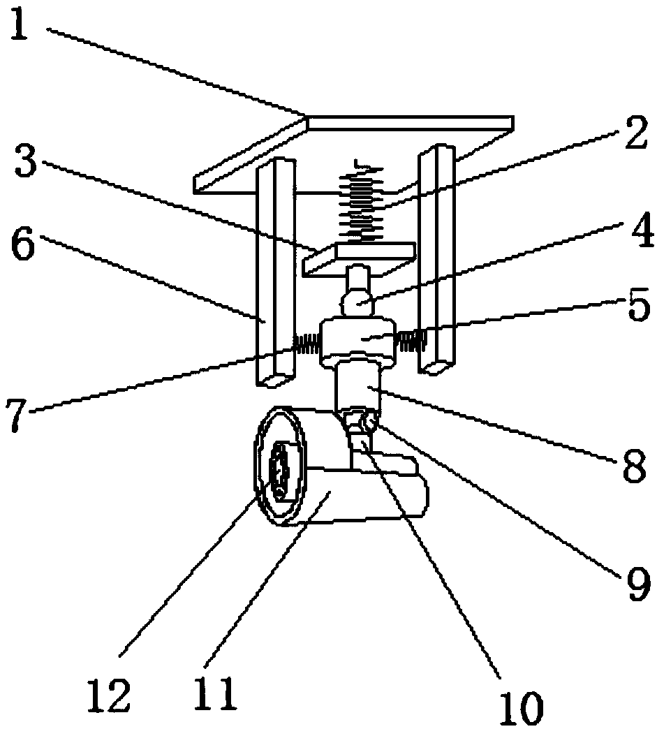
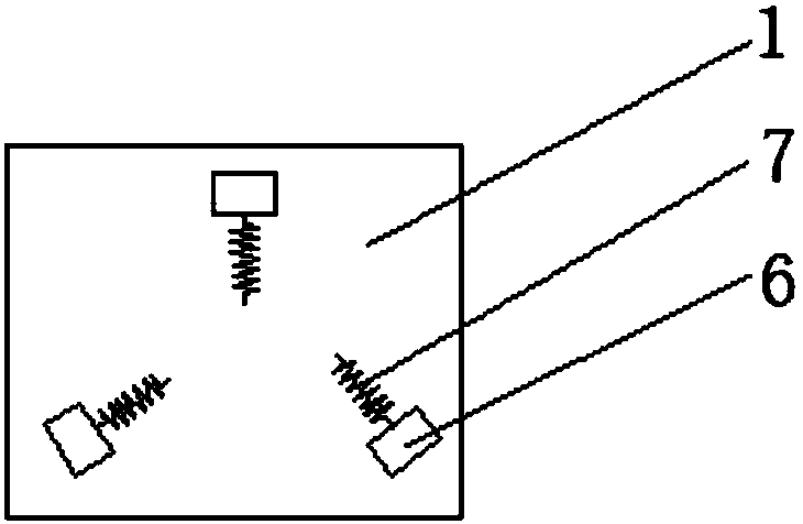
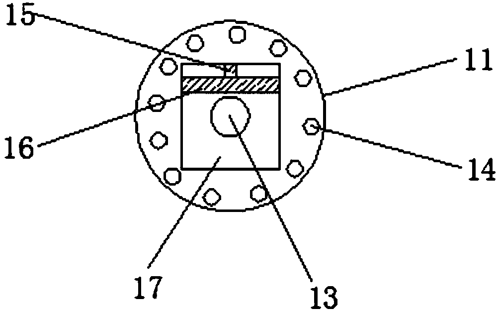
[0037] Such as Figure 1-5 As shown, the present invention provides a kind of multifunctional camera head, and described multifunctional camera head comprises: The described camera head that is used for bus comprises: top board 1, buffer member 2, connecting plate 3, fixing column connected sequentially from top to b...


PUM


Abstract

The invention discloses a multifunctional camera. The camera for a bus comprises a top plate, a buffer element, a connection plate, a fixing post and a camera body which are connected in sequence fromtop to bottom. Three buffer rods are at least set on the lower surface of the top plate. The three buffer rods are set in an equilateral triangle. The fixing post is located at the center of the three buffer rods. A first buffer spring is set between sides of each buffer rod and the fixing post. A storage slot is set on the camera body. A lens is set in the storage slot. A drive pump is also setin the camera body. A piston rod on the drive pump stretches out to the storage slot. A cleaning plate is connected with the piston rod. The drive pump can periodically drive the cleaning plate to move along the bottom surface of the storage slot through piston rod. According to the multifunctional camera, the problem that the camera in the prior art is relatively single in function, has no automatic cleaning function and is liable to shake to result in unclear photographing when the camera is employed in a moving environment such as the bus is overcome.

Description

technical field [0001] The invention relates to the field of cameras, in particular to a multifunctional camera. Background technique [0002] Camera (CAMERA or WEBCAM), also known as computer camera, computer eye, electronic eye, etc., is a video input device, which is widely used in video conferencing, telemedicine and real-time monitoring, etc., which greatly facilitates our life. Anti-theft and monitoring play an important role. [0003] However, the camera in the prior art has a single function, only provides a shooting function, and does not have the function of automatic cleaning, and when the camera is used in a mobile environment such as a bus, it is easy to shake and cause the shooting to be unclear or even impossible to shoot. [0004] Therefore, it is an urgent problem to be solved by the present invention to provide a multi-function camera that has its own lens cleaning function during use, is also anti-vibration, and can be used normally in a shaking environme...

Claims


Application Information

Patent Timeline
IPC IPC(8): H04N5/232G03B17/56B60R11/04F16F15/04G03B30/00
CPCG03B17/561F16F15/04B60R11/04H04N23/682H04N23/68
Inventor 杨潘李军杨晓沛张飞朱仕达
Owner ANHUI DAER INTELLIGENT CONTROL SYST
Why Eureka
Try Eureka