Electroplating method for metal inserts in electroacoustic devices

A technology of metal inserts and electroacoustic devices, applied in electrolytic components, electrical components, sensors, etc., to achieve the effect of improving stability and salt spray resistance

Active Publication Date: 2020-09-18
GOERTEK INC
View PDF5 Cites 0 Cited by
  • Summary
  • Abstract
  • Description
  • Claims
  • Application Information

AI Technical Summary

Problems solved by technology

[0005] The purpose of the present invention is to provide an electroplating method for metal inserts in electro-acoustic devices to solve the stability and salt spray resistance of existing electro-acoustic device products containing metal inserts formed by metal injection molding processes

Method used


Image

  • Electroplating method for metal inserts in electroacoustic devices
  • Electroplating method for metal inserts in electroacoustic devices
  • Electroplating method for metal inserts in electroacoustic devices

Examples


Embodiment Construction

[0026] In order to illustrate the present invention more clearly, the present invention will be further described below in conjunction with preferred embodiments and accompanying drawings. Similar parts in the figures are denoted by the same reference numerals. Those skilled in the art should understand that the content specifically described below is illustrative rather than restrictive, and should not limit the protection scope of the present invention.

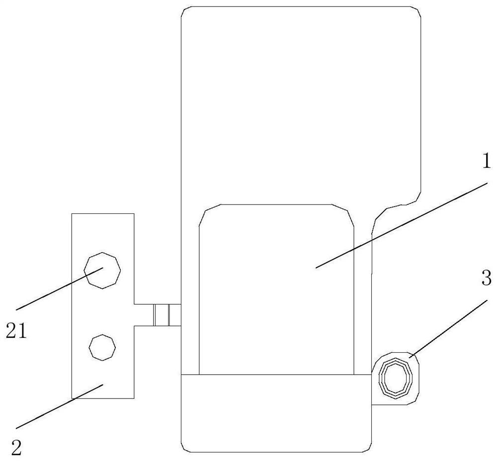
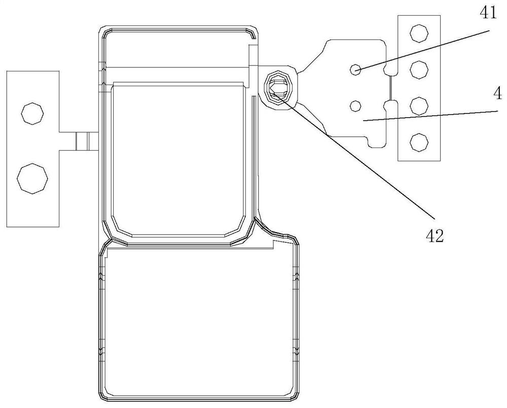
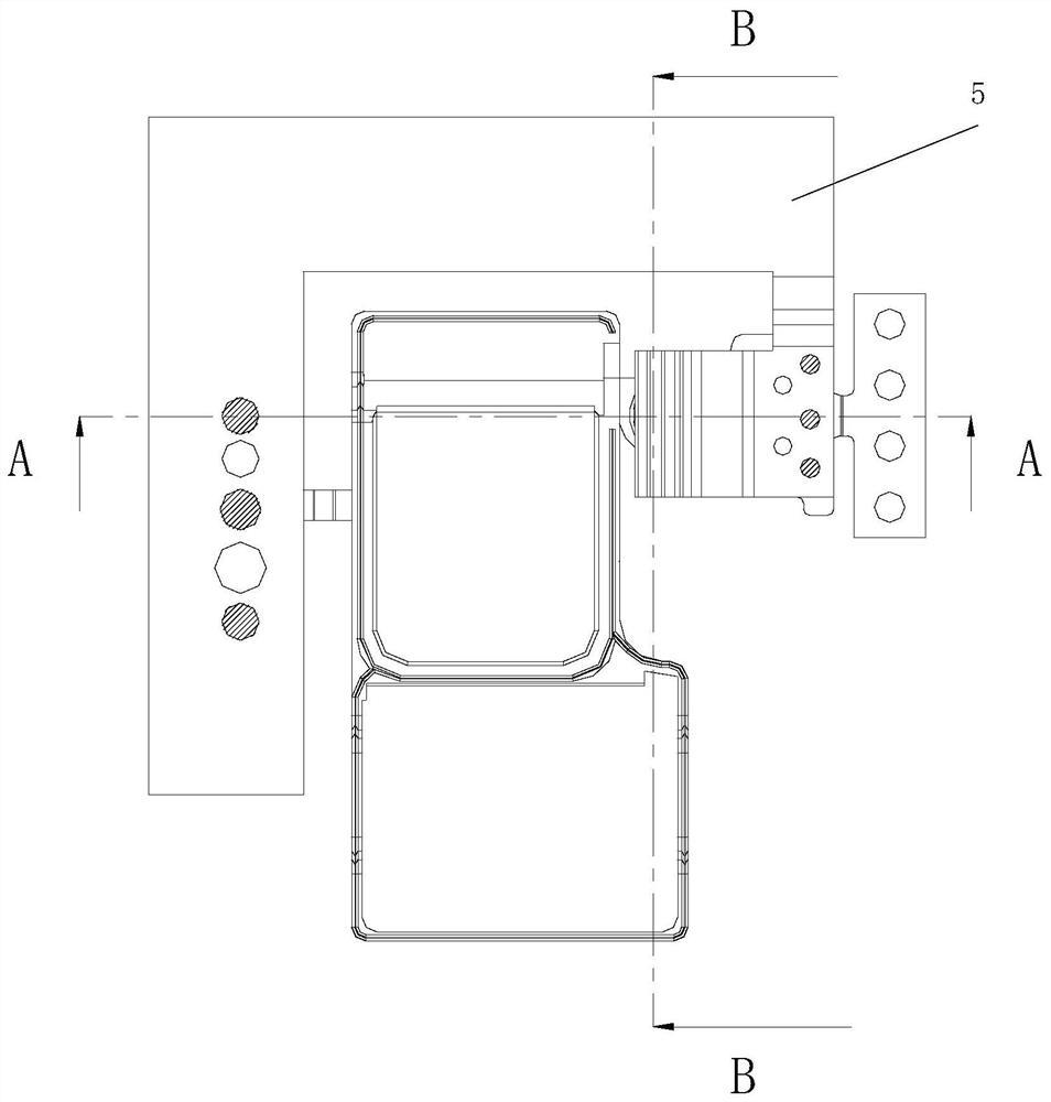
[0027] combine Figure 1-Figure 3 One embodiment of the present invention provides a method for electroplating a metal insert in a loudspeaker, the method comprising the steps of:

[0028] A loudspeaker blank is provided, wherein the blank includes a metal stamping part 1, a connecting strip 2 connecting the metal stamping part 1 and extending to the outside of the blank, and a metal insert, the metal insert including a The fitting part 3 outside the green body;

[0029] Electrically connecting one end of the connecting ...


PUM


Abstract

The invention discloses an electroplating method of a metal insert in an electroacoustic device. The method comprises the following steps: providing an electroacoustic device blank, wherein the blankcomprises a metal stamping part, a material connecting strip connected with the metal stamping part and extending to the outside of the blank, and the metal insert, and the metal insert comprises an embedding part located at the outside of the blank; electrically connecting one end of the material connecting strip with the embedding part through an electric conduction member; and electroplating the blank through the material connecting strip so as to achieve the electroplating of the metal insert in the electroacoustic device. By adoption of the electroplating method, the secondary electroplating of the metal insert in the electroacoustic device, especially the metal insert injection molded by metal, thereby improving the stability and salt spray resistance of the obtained electroacousticdevice product.

Description

technical field [0001] The invention relates to the technical field of electroacoustic conversion. More specifically, it relates to an electroplating method for metal inserts in electroacoustic devices. Background technique [0002] A steel sheet is usually provided in the speaker (SPK), so that when the speaker is installed in an electronic device, the steel sheet is in electrical contact with a soldering pad of a PCB to connect the voice coil of the speaker to an external circuit. At present, the conventional method of installing the steel sheet in the loudspeaker is to assemble the steel sheet with the injection-molded product through the plug-in structure. This method flexibly selects the position of the steel sheet, but it has low assembly accuracy and poor connection. There is also the problem of firmness; there is also a steel sheet with a conductive connecting strip formed by stamping, and then the steel sheet is placed where it needs to be placed, and then the prod...

Claims


Application Information

Patent Timeline
Patent Type & Authority Patents(China)
IPC IPC(8): H04R31/00C25D7/00C25D17/08
CPCC25D7/00C25D17/007C25D17/08H04R31/003
Inventor 伦英军张庆一曹广飞
Owner GOERTEK INC
Why Eureka
Try Eureka