A high-efficiency electric automatic dust removal device

A technology of electrical automation and dust removal device, which is applied in the direction of combination device, gas treatment, chemical instrument and method, etc. It can solve the problems of life safety of crisis factory workers, damage to dust removal device, and high labor intensity, so as to achieve fast dust removal speed and prevent pollution , Improve the effect of dust removal efficiency

Active Publication Date: 2021-05-25
江苏工腾自控阀门有限公司
View PDF6 Cites 0 Cited by
  • Summary
  • Abstract
  • Description
  • Claims
  • Application Information

AI Technical Summary

Problems solved by technology

The clean room requires that no matter how the external air conditions change, the room can maintain the cleanliness, temperature, humidity and pressure of the original set requirements, so stability is particularly important; in industrial production, boilers are used. A large amount of flue gas will be generated during the working process of the boiler. If it is directly discharged, it will cause serious pollution to the external environment and endanger the life safety of factory workers; The cost is expensive, and the dust removal device absorbs a large amount of impurities during the dust removal process, which will also cause damage to the dust removal device. After the dust removal device is turned on, no matter whether the concentration of dust is high or low, the dust removal device will always work, which is undoubtedly a waste of unnecessary energy consumption; therefore, it is necessary to design an energy-saving electrified dust removal device

Method used


Image

  • A high-efficiency electric automatic dust removal device
  • A high-efficiency electric automatic dust removal device
  • A high-efficiency electric automatic dust removal device

Examples


Embodiment Construction

[0020] The following will clearly and completely describe the technical solutions in the embodiments of the present invention with reference to the accompanying drawings in the embodiments of the present invention. Obviously, the described embodiments are only some, not all, embodiments of the present invention. Based on the embodiments of the present invention, all other embodiments obtained by persons of ordinary skill in the art without making creative efforts belong to the protection scope of the present invention.

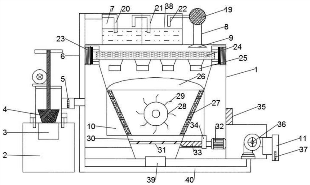
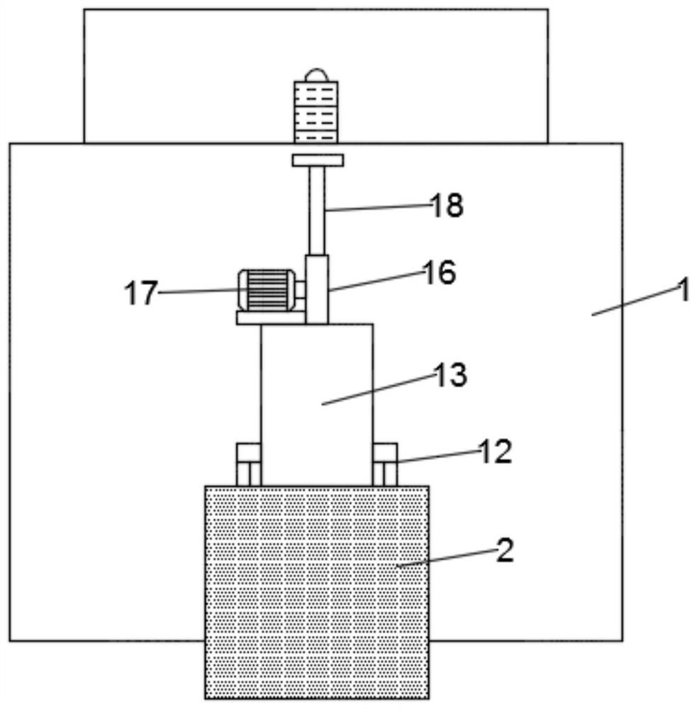
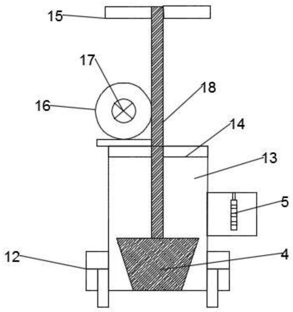
[0021] see Figure 1~3, in an embodiment of the present invention, a high-efficiency electric automatic dust removal device includes a dust removal chamber 1, a smoke discharge chamber 2, a smoke discharge port 3, a piston valve 4, a first smoke sensor 5 and a first absorption liquid storage tank 7. A smoke discharge chamber 2 is arranged on the left side of the dust removal chamber 1, a smoke discharge port 3 is arranged on the upper part of the inner cavity ...


PUM


Abstract

The invention discloses a high-efficiency electric automatic dust removal device, which comprises a dust removal chamber, a smoke discharge chamber, a smoke discharge port, a piston valve and a first absorption liquid storage box. The left side of the dust removal chamber is provided with a smoke discharge chamber. The upper part of the inner cavity of the smoke discharge chamber is provided with a smoke outlet, and the upper part of the smoke discharge chamber is provided with a smoke escape chamber; the lower part of the inner cavity of the smoke escape chamber is provided with a piston valve; the position of the piston valve is set at The upper part of the smoke outlet; the right side of the smoke escape chamber is fixedly connected to the first connecting pipe; the upper end of the first connecting pipe is fixedly connected to the first absorption liquid storage tank; the right side of the first absorption liquid storage tank is fixedly installed The second absorption liquid storage tank; the invention has reasonable design, high dust removal efficiency and fast dust removal speed, can avoid direct contact between workers and boiler flue gas, can also prevent boiler flue gas from polluting the external environment, is energy-saving and environmentally friendly, and is suitable for popularization.

Description

technical field [0001] The invention relates to the technical field of electric dust removal, in particular to a high-efficiency electric automatic dust removal device. Background technique [0002] Electric dust removal device refers to the removal of particulates, harmful air, bacteria and other pollutants in the air within a certain space, and the indoor temperature, cleanliness, indoor pressure, air velocity and air distribution, noise vibration and lighting, static electricity, etc. Control within a certain range of needs, and give a specially designed room. The clean room requires that no matter how the external air conditions change, the room can maintain the cleanliness, temperature, humidity and pressure of the original set requirements, so stability is particularly important; in industrial production, boilers are used. A large amount of flue gas will be generated during the working process of the boiler. If it is directly discharged, it will cause serious pollutio...

Claims


Application Information

Patent Timeline
Patent Type & Authority Patents(China)
IPC IPC(8): B01D50/00B01D53/26
CPCB01D50/00B01D53/26B01D2258/0283
Inventor 陈阳
Owner 江苏工腾自控阀门有限公司
Why Eureka
Try Eureka