Fork frame
A technology of fork frame and support frame, which is applied in the field of fork frame, can solve problems such as difficulty in adapting to the production environment, and achieve the effects of simple and light structure, wide applicability, and reduced labor intensity
- Summary
- Abstract
- Description
- Claims
- Application Information
AI Technical Summary
Problems solved by technology
Method used
Image

Examples
Embodiment 1
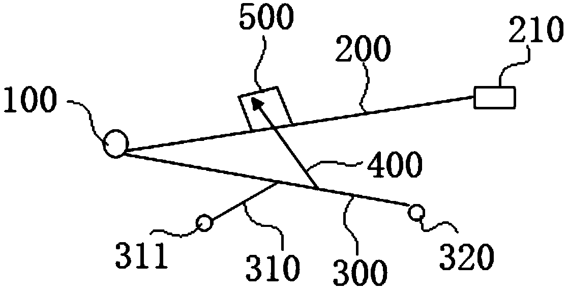
[0037] Such as figure 1 As shown, a kind of fork frame of the present embodiment comprises movable support 200 and support frame 300, and support frame 300 is provided with push rod 400, and the telescoping end of this push rod 400 is connected with movable support 200, and the free end of movable support 200 A joint 210 is provided, wherein the joint 210 refers to a special joint specially fixed with the equipment to be installed, maintained or moved. The joint 210 can be equipped with a set of standard joints or special joints of the opposite sex according to the use requirements, so as to solve different use requirements and different The needs of the use environment. The specific design and structure of the connector 210 are common means known in the industry, and will not be described in detail here.
[0038] This embodiment also includes a handle 100, one end of the movable bracket 200 and the support frame 300 are respectively arranged on the handle 100, and the movabl...
Embodiment 2
[0044] A kind of fork frame of this embodiment, the basic structure is the same as that of Embodiment 1. Furthermore, the push rod 400 in this embodiment is a hydraulic push rod, and the push rod 400 is provided with a check valve for preventing falling, and for The load-limiting safety valve helps to ensure production safety and the service life of the overall device.
[0045] In this embodiment, the movable support 200 is a telescopic support, which can adopt conventional telescopic structures in various industries. For example, multi-section telescopic tubes can be arranged to be telescopically fixed through pin holes and pins. Similarly, the support frame 300 can also be According to the needs of use, it can be set as a flexible structure. The telescopic setting of the movable support 200 is helpful for placement and use in the non-use state and the narrow area state, and also helps to increase the length of the movable support 200 according to the use requirements, thereb...
Embodiment 3
[0047] A kind of fork frame of this embodiment, the basic structure is the same as that of Embodiment 2. Furthermore, in this embodiment, an adjustment box 500 is arranged above the movable support 200, and the telescopic end of the push rod 400 is connected with the adjustment box 500. The box 500 is a hollow box structure, the telescopic end of the push rod 400 passes through the cavity of the box body and is connected with the top wall of the adjustment box 500, the bottom of the adjustment box 500 is connected with the movable bracket 200, and the bottom of the adjustment box 500 is Open structure, the size of the opening can accommodate the size of the power cylinder of the push rod 400 . When the push rod 400 shrinks downward, it drives the adjustment box 500 and the movable support 200 to shrink downward synchronously, and when the push rod 400 goes up, it drives the adjustment box 500 and the movable support 200 to move upward synchronously.
[0048] The setting of the...
PUM
 Abstract
Description
Claims
Application Information