Oil collecting recycling system

A recovery system and oil collection technology, which is applied in the field of lubrication, can solve the problems that lubricant has no fluidity, is easily located between two rotating parts, and cannot penetrate, so as to reduce wear and facilitate recycling

Active Publication Date: 2018-08-07
CHONGQING IND POLYTECHNIC COLLEGE
View PDF9 Cites 1 Cited by
  • Summary
  • Abstract
  • Description
  • Claims
  • Application Information

AI Technical Summary

Problems solved by technology

[0002] Chains are often used on bicycles. Lubricating oil is usually applied to new chains, and the lubricating oil is generally attached to the surface of the chain. Since dry oil lubricants have no fluidity, they cannot penetrate into the chain pins that need to be lubricated, resulting in chain pins. There is a lack of lubricating oil at the connection between the inner chain plate and the outer chain plate, and it is impossible to achieve a comprehensive lubrication effect at all
[0003] At the same time, after the chain is used for a long time, the various parts in the chain will rub against each other, and the debris generated during the friction process will be integrated into the lubricating oil on the chain. After the lubricating oil adheres to the debris during this process, the lubricating ability is reduced At the same time, the debris in the lubricating oil is easy to be located between the two rotating parts, which will increase the wear between the parts. Therefore, when the lubricating oil on the chain turns black or is extremely dry, it is necessary to clean the chain and re-oil it
[0004] The common chain maintenance method is to clean the whole chain directly, and then re-oil the whole chain as a whole after cleaning. The problem that the connection between the plate and the outer chain plate is not coated with lubricating oil

Method used


Image

  • Oil collecting recycling system
  • Oil collecting recycling system
  • Oil collecting recycling system

Examples


Embodiment Construction

[0018] Further detailed explanation through specific implementation mode below:

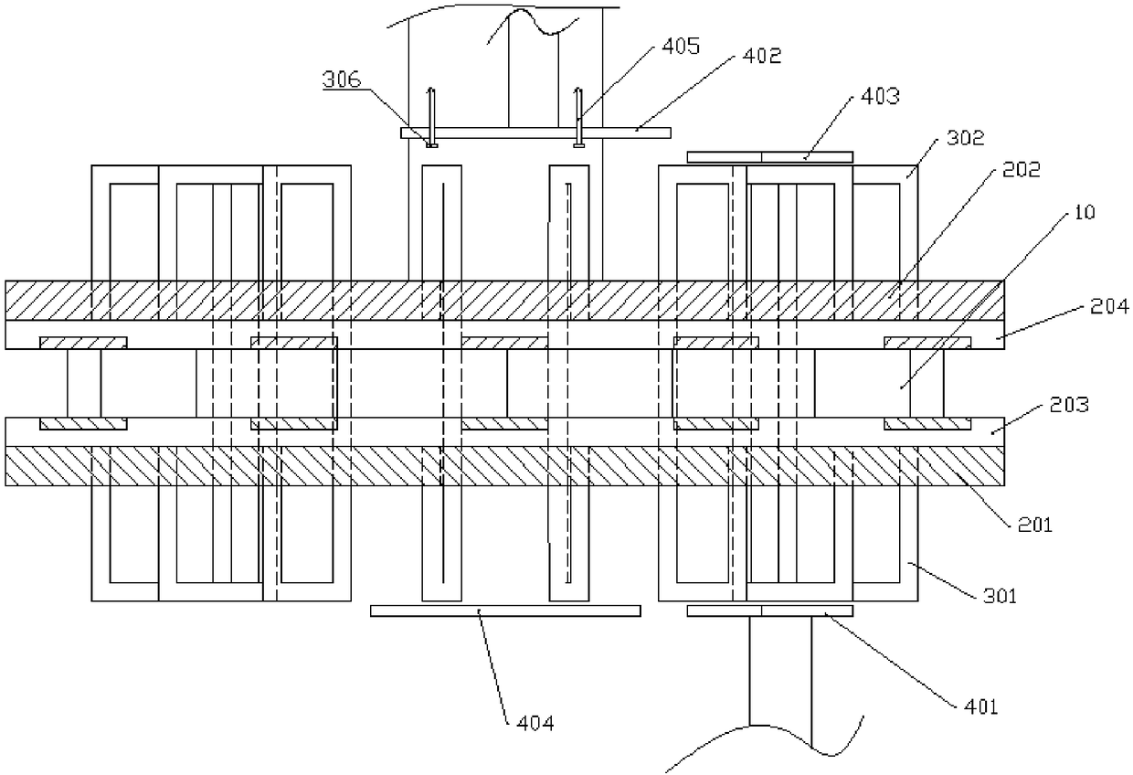
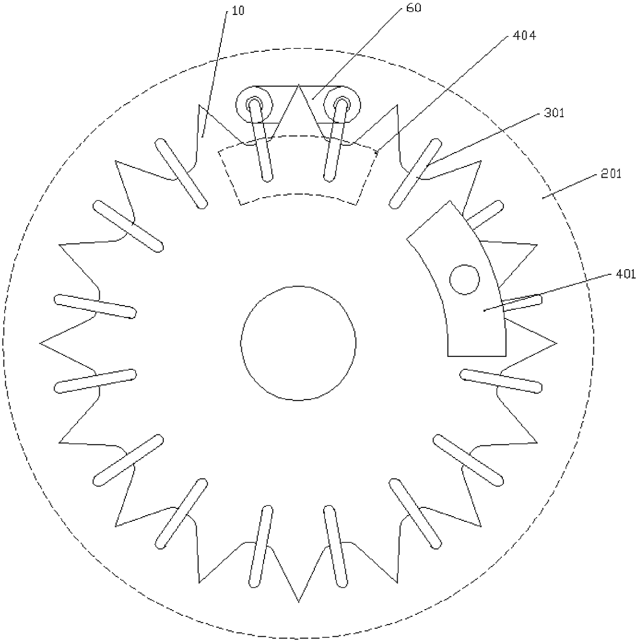
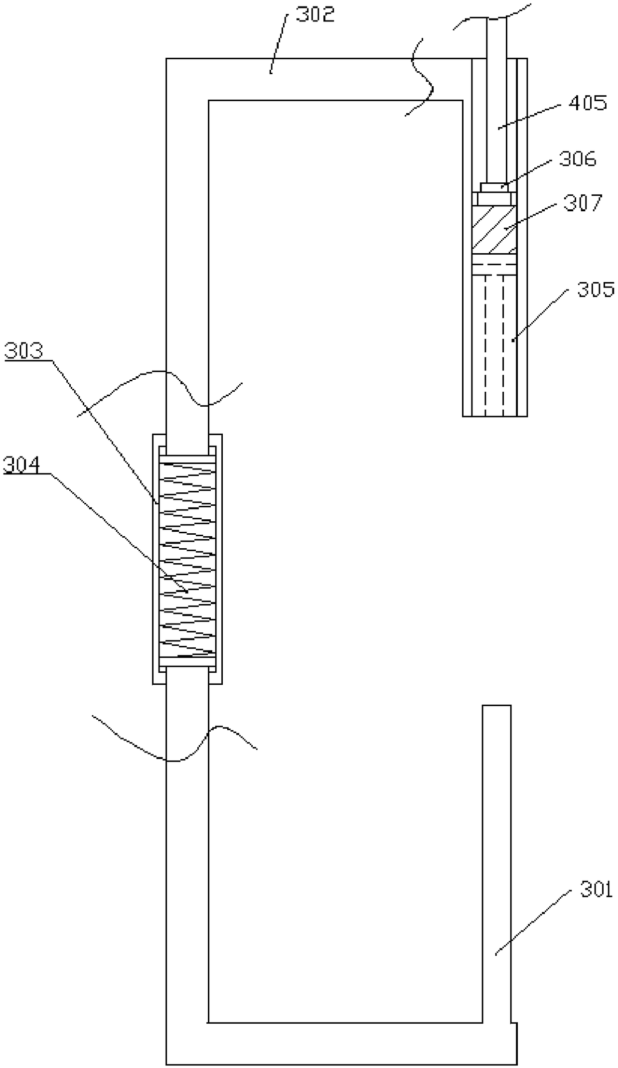
[0019] The reference signs in the drawings of the description include: sprocket 10, first mounting block 201, second mounting block 202, first limiting groove 203, second limiting groove 204, push rod 301, oiling rod 302, sleeve Barrel 303 , spring 304 , accommodating cavity 305 , push block 306 , oil-absorbing sponge 307 , first top plate 401 , second top plate 402 , first support plate 403 , second support plate 404 , push rod 405 , and chain 60 .

[0020] The embodiment is basically as attached figure 1 , attached figure 2 And attached image 3 Shown: the oil collection recovery system, including the rotating sprocket 10, support mechanism, installation mechanism and oiling mechanism.

[0021] The installation mechanism includes a first installation block 201 and a second installation block 202, the first installation block 201 and the second installation block 202 are ring-shaped and made...


PUM


Abstract

The invention relates to the field of lubricating, and particularly discloses an oil collecting recycling system. The oil collecting recycling system comprises a mounting mechanism and an oil applyingmechanism; the mounting mechanism comprises an elastic first mounting block and an elastic second mounting block; both the first mounting block and the second mounting block are annular; the first mounting block is coaxially welded at one end of a chain wheel; the second mounting block is coaxially welded at the other end of the chain wheel; a first limiting groove is formed in the first mountingblock; a second limiting groove is formed in the second mounting block; the first limiting groove and the second limiting groove are opposite to the chain teeth of the chain wheel; the oil applying mechanism comprises pushing rods and oil applying rods; first through holes for the pushing rods to slide are formed in the first mounting block; second through holes for the oil applying rods to slideare formed in the second mounting block; an accommodating cavity is formed in one end of the oil applying rod; a pushing block and oil absorbing sponge are mounted in the accommodating cavity. According to the scheme, connecting parts between a chain pin and an inner chain plate as well as an outer chain plate can be coated with lubricating oil.

Description

technical field [0001] The invention belongs to the field of lubrication, in particular to an oil collection and recovery system. Background technique [0002] Chains are often used on bicycles. Lubricating oil is usually applied to new chains, and the lubricating oil is generally attached to the surface of the chain. Since dry oil lubricants have no fluidity, they cannot penetrate into the chain pins that need to be lubricated, resulting in chain pins. The connection with the inner chain plate and the outer chain plate lacks the effect of lubricating oil, and it cannot play a comprehensive lubricating effect at all. [0003] At the same time, after the chain is used for a long time, the various parts in the chain will rub against each other, and the debris generated during the friction process will be integrated into the lubricating oil on the chain. After the lubricating oil adheres to the debris during this process, the lubricating ability is reduced At the same time, th...

Claims


Application Information

Patent Timeline
Patent Type & Authority Applications(China)
IPC IPC(8): F16N11/08
CPCF16N11/08
Inventor 朋宇姚雪儒何婉亭何明黄月欧阳婧芸
Owner CHONGQING IND POLYTECHNIC COLLEGE
Why Eureka
Try Eureka