Supercharge Your Innovation With Domain-Expert AI Agents!

Machine room air flow organization control system and method

A technology of airflow organization and control system, applied in heating and ventilation control system, control input related to air characteristics, heating and ventilation safety system, etc. To eliminate problems such as cold spots, to achieve the effect of eliminating unreasonable air flow organization, improving energy efficiency, and improving the degree of greening

Pending Publication Date: 2018-08-07
SHANGHAI GRANDWAY TELECOM TECH
View PDF0 Cites 0 Cited by
  • Summary
  • Abstract
  • Description
  • Claims
  • Application Information

AI Technical Summary

Benefits of technology

This technology helps optimize heat distribution within an office by gather multiple point'temperature measurements from different parts inside it. These measurement values are then sent back into the system for analysis based on factors like power usage, equipment capacity, workload requirements etc., which help improve overall performance and reduce costs associated with maintaining comfortable temperatures indoors during working hours.

Problems solved by technology

The technical problem addressed during this patented process relates to improving the performance and effectiveness of an electronic device's thermal management system for efficient operation within its environment. Unhealthy conditions such as excessive humidity may cause damage from overheated components and poorly designed systems with insufficient fans. To address these issues, there has been developed methods called active convection control techniques which aim at controlling the movement of warm/cold particles towards each other inside the housing while keeping them moving freely without interferring with their intended function. These improvements help maintain proper temperatures and prevent condensations on certain parts like circuit boards caused by too high internal pressure.

Method used


Image

  • Machine room air flow organization control system and method
  • Machine room air flow organization control system and method

Examples


Embodiment 1

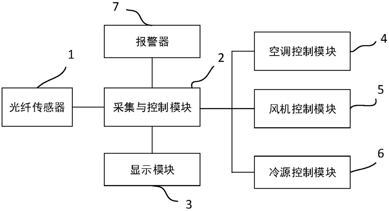
[0026] This embodiment provides a computer room air distribution control system, such as figure 1 As shown, it includes an optical fiber sensor 1, an acquisition and control module 2, a display module 3, an air conditioner control module 4, a fan control module 5 and a cold source control module 6, the optical fiber sensor 1 and the acquisition and control module A control module 2, the acquisition and control module 2 is electrically connected to the display module 3, the air conditioner control module 4, the fan control module 5 and the cold source control module 6;

[0027] The optical fiber sensor 1 is arranged in the cabinet of the computer room, specifically at the front door and the back door of the cabinet of the computer room, and the optical fiber sensor 1 is used to collect temperature data at multiple points in the space of the cabinet, and output a temperature signal to the acquisition and control module 2;

[0028] The collection and control module 2 is configur...

Embodiment 2

[0042] This embodiment provides a method for controlling airflow organization in a computer room, such as figure 2 As shown, it is implemented using the computer room airflow control system described in Embodiment 1, including:

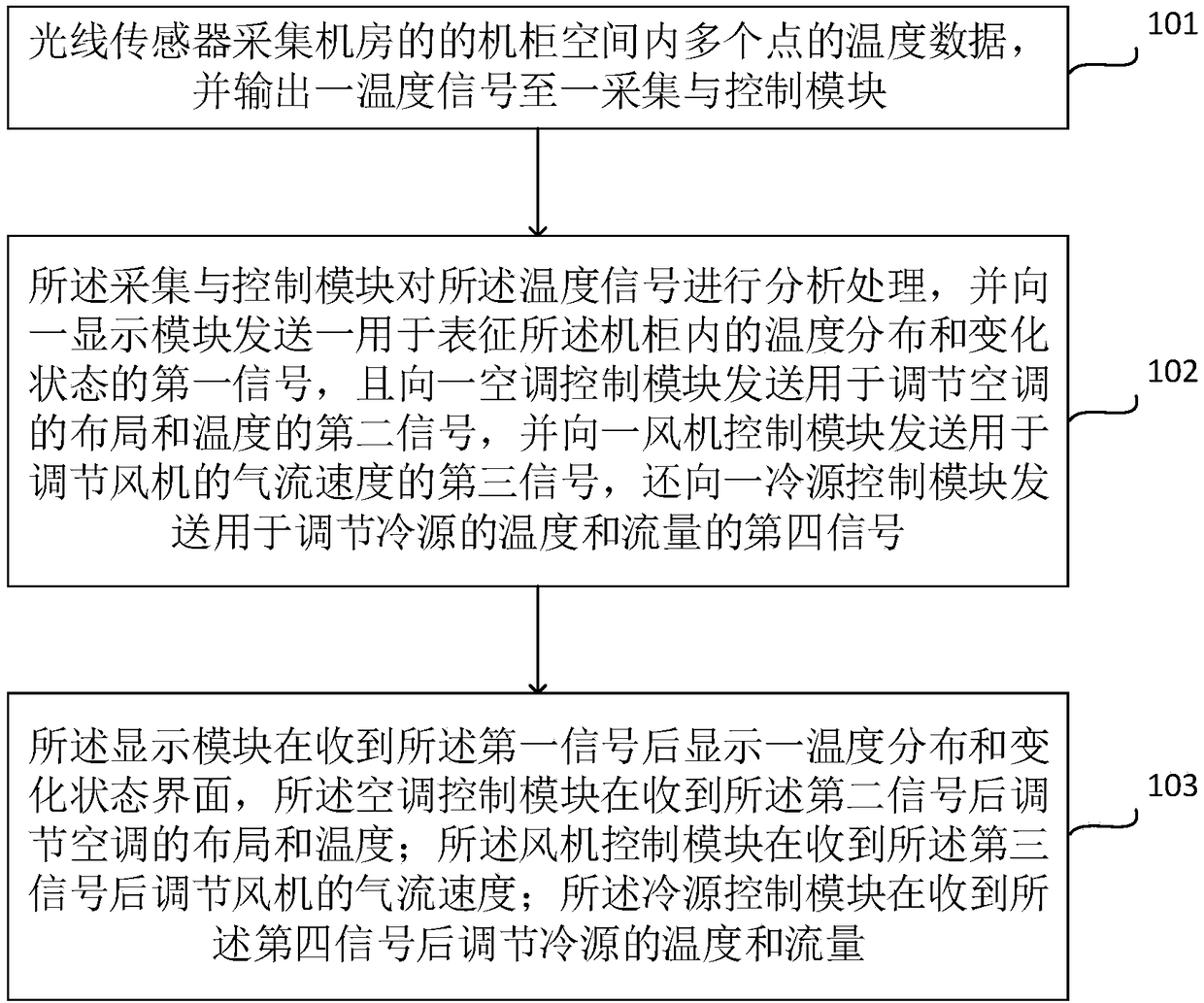
[0043] Step 101, the light sensor collects temperature data at multiple points in the cabinet space of the computer room, and outputs a temperature signal to a collection and control module;

[0044] Step 102, the acquisition and control module analyzes and processes the temperature signal, and sends a first signal representing the temperature distribution and changing state in the cabinet to a display module, and sends a first signal to an air-conditioning control module The second signal for adjusting the layout and temperature of the air conditioner, and the third signal for adjusting the airflow speed of the fan is sent to a fan control module, and the third signal for adjusting the temperature and flow of the cold source is sent to a cold source...


PUM


Abstract

The invention discloses a machine room air flow organization control system and method. The system comprises an optical fiber sensor, a collecting and control module, a display module, an air conditioner control module, a fan control module and a cold source control module. The optical fiber sensor and the collecting and control module are electrically connected. The collecting and control moduleis electrically connected with the display module, the air conditioner control module, the fan control module and the cold source control module. The optical fiber sensor is used for collecting temperature data of a machine cabinet and outputting a temperature signal. The collecting and control module is used for sending a first signal, a second signal, a third signal and a fourth signal to the display module, the air conditioner control module, the fan control module and the cold source control module. The air conditioner control module is used for adjusting distribution and the temperature of an air conditioner. The fan control module is used for adjusting the air flow speed of a fan. The cold source control module is used for adjusting the temperature and flow amount of a cold source. According to the scheme, local hot points or cold points of a machine room are eliminated, and optimization and energy-saving control of air flow organization are achieved.

Description


Claims


Application Information

Patent Timeline
Owner SHANGHAI GRANDWAY TELECOM TECH
Features
  • R&D
  • Intellectual Property
  • Life Sciences
  • Materials
  • Tech Scout
  • Unparalleled Data Quality
  • Higher Quality Content
  • 60% Fewer Hallucinations
Learn More