Permanent-magnetic vacuum on-load voltage-regulating tapping switch

A permanent magnet vacuum and tap changer technology, applied in electrical switches, electrical components, circuits, etc., can solve the problems of poor reliability of components, complicated switching process, limited volume reduction, etc. The effect of miniaturized design

Pending Publication Date: 2018-08-07
ZHEJIANG TENGLONG ELECTRICAL APP
View PDF1 Cites 3 Cited by
  • Summary
  • Abstract
  • Description
  • Claims
  • Application Information

AI Technical Summary

Problems solved by technology

The switching process of the device is complicated, the reliability of components is poor, and the volume reduction is also limited

Method used


Image

  • Permanent-magnetic vacuum on-load voltage-regulating tapping switch
  • Permanent-magnetic vacuum on-load voltage-regulating tapping switch
  • Permanent-magnetic vacuum on-load voltage-regulating tapping switch

Examples


Embodiment 1

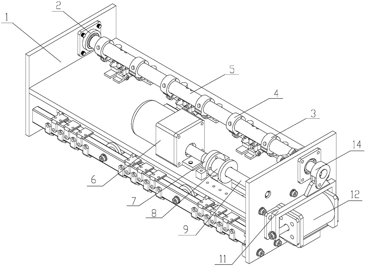
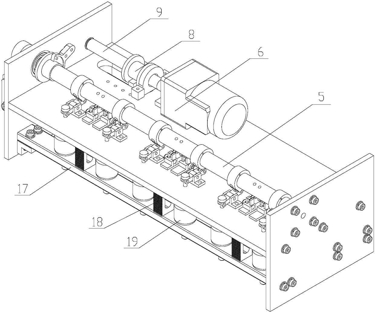
[0027] like figure 1 , Figure 3 to Figure 6 The shown permanent magnet vacuum on-load tap changer includes a gear selection mechanism and a circuit switching mechanism, and the gear selection mechanism is provided with a plurality of fixed contacts and a first movable contact 34 matched therewith; The circuit switching mechanism includes a permanent magnet mechanism 12, a switch, a vacuum tube 19 and a transition resistor 18; the gear selection mechanism and the circuit switching mechanism are arranged in parallel, and it is characterized in that: the switch includes a rotating shaft 5, a switching contact mechanism And the lever mechanism, the permanent magnet mechanism 12 drives the rotating shaft 5 to rotate, the rotating shaft 5 drives the lever mechanism to close or disconnect the vacuum tube 19, and the rotating shaft 5 drives the switching contact mechanism to move.

[0028] The rotating shaft 5 is provided with three groups of cams, each group of cams includes a firs...

Embodiment 2

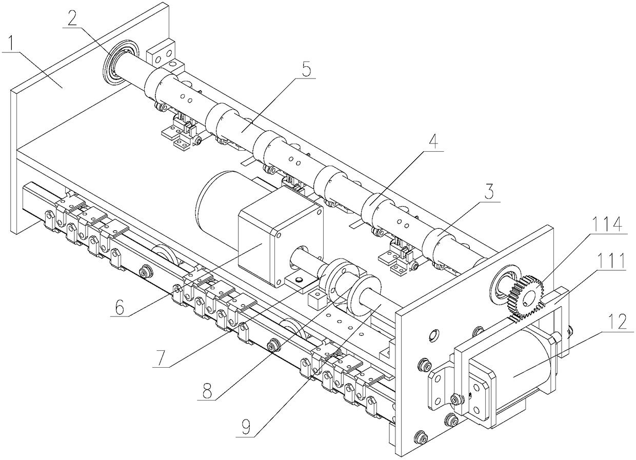
[0039] The difference between this embodiment and embodiment 1 is: as figure 2 As shown, the permanent magnet mechanism 12 is provided with a rack 111, and one end of the rotating shaft 5 is provided with a gear 114, the rack 111 meshes with the gear 114, and the rack 111 promotes the rotation of the gear 114 to drive the rotation of the rotating shaft 5 .

[0040] like Figure 7 As shown, after the present invention receives the voltage regulation instruction, the deceleration motor is started first, and the first movable contact is driven by the screw rod and the screw rod slider to select the gear position. After the gear position is selected, the motor stops, and then returns the signal Command the permanent magnet action, the shaft rotates through the first cam and the second cam so that one vacuum tube is switched from the open state to the closed state, and the other vacuum tube is switched from the closed state to the open state. During the rotation of the shaft, the...


PUM


Abstract

The invention relates to a permanent-magnetic vacuum on-load voltage-regulating tapping switch. The permanent-magnetic vacuum on-load voltage-regulating tapping switch comprises a gear selecting mechanism and a circuit switching mechanism, wherein the gear selecting mechanism is provided with a plurality of fixed contacts and a first moving contact matched with the fixed contacts; the circuit switching mechanism comprises a permanent-magnet mechanism, a selector switch, a vacuum tube and a transition resistor; the gear selecting mechanism and the circuit switching mechanism are parallel. The permanent-magnetic vacuum on-load voltage-regulating tapping switch is characterized in that the selector switch comprises a rotary shaft, a selector contact mechanism and a lever type mechanism; the permanent-magnet mechanism drives the rotary shaft to rotate; the rotary shaft drives the lever type mechanism to be connected with or disconnected from the vacuum tube, and drives the switching contact mechanism to move. The permanent-magnetic vacuum on-load voltage-regulating tapping switch has the beneficial effects that a reasonable layout and a miniaturization design are adopted in the designprocess, so that the overall dimension of a product is further reduced, and more space is saved for designing a transformer.

Description

technical field [0001] The invention relates to a tap changer, in particular to a permanent magnet vacuum on-load tap changer. Background technique [0002] Most of the on-load tap-changers used in the power supply department adopt a cylindrical structure with a cylindrical shape. It is composed of an insulating cylinder, a main shaft, a mounting bracket, a conductive ring, a moving contact and a static contact. Its static contact The contacts are distributed on the inner wall of the insulating cylinder. Since the static contacts need to have a certain length, and an appropriate gap must be maintained between adjacent static contacts to prevent leakage or arc breakdown, the diameter and circumference of the inner wall of the insulating cylinder The length directly determines the maximum number of gears that the tap changer can set. A tap changer with more gears requires a larger diameter of the insulating cylinder and a larger volume of the switch. Moreover, the correspond...

Claims


Application Information

Patent Timeline
Patent Type & Authority Applications(China)
IPC IPC(8): H01H9/00
CPCH01H9/0011H01H9/0027H01H9/0038
Inventor 章宏仁叶韩超
Owner ZHEJIANG TENGLONG ELECTRICAL APP
Why Eureka
Try Eureka