Eureka AIR delivers breakthrough ideas for toughest innovation challenges, trusted by R&D personnel around the world.

Electronic equipment vibration control method, device, readable storage medium and electronic equipment

A technology of electronic equipment and control instructions, which is applied in the field of electronic equipment and vibration control of electronic equipment, can solve the problems of lack of flexibility and cannot meet the needs of users, and achieve the effect of convenient and controllable vibration intensity, low cost, and avoiding delay phenomenon

Active Publication Date: 2020-12-01
GUANGDONG OPPO MOBILE TELECOMM CORP LTD
View PDF6 Cites 0 Cited by
  • Summary
  • Abstract
  • Description
  • Claims
  • Application Information

AI Technical Summary

Problems solved by technology

However, the vibration intensity of the rotor motor is fixed and cannot be changed by the user, which lacks flexibility, and there will be a certain delay when the rotor motor starts, which cannot meet the needs of users

Method used


Image

  • Electronic equipment vibration control method, device, readable storage medium and electronic equipment
  • Electronic equipment vibration control method, device, readable storage medium and electronic equipment
  • Electronic equipment vibration control method, device, readable storage medium and electronic equipment

Examples


Embodiment Construction

[0058] Embodiments of the present invention are described in detail below, examples of which are shown in the drawings, wherein the same or similar reference numerals designate the same or similar elements or elements having the same or similar functions throughout. The embodiments described below by referring to the figures are exemplary and are intended to explain the present invention and should not be construed as limiting the present invention.

[0059] The vibration control method and device for electronic equipment and electronic equipment according to the embodiments of the present invention will be described below with reference to the accompanying drawings.

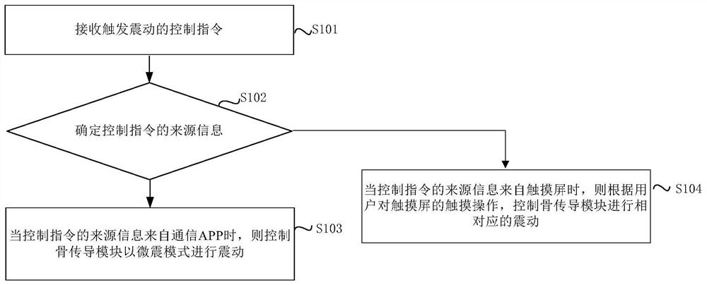
[0060] figure 1 It is a flowchart of a vibration control method for an electronic device proposed by an embodiment of the present invention.

[0061] Such as figure 1 As shown, the electronic device vibration control method includes the following steps:

[0062] Step 101, receiving a control instruction for t...


PUM


Abstract

The invention discloses a vibration control method and device for electronic equipment, and electronic equipment, wherein the vibration control method for electronic equipment includes: receiving a control instruction for triggering vibration; determining the source information of the control instruction; when the source information of the control instruction comes from a communication APP , the bone conduction module is controlled to vibrate in a micro-vibration mode; or when the source information of the control command comes from the touch screen, the bone conduction module is controlled to vibrate correspondingly according to the user's touch operation on the touch screen. In the electronic equipment vibration control method, device and electronic equipment of the embodiments of the present invention, a smaller bone conduction module is added to the electronic equipment to replace a larger and more expensive motor, the vibration intensity is convenient and controllable, and the cost is lower. Using bone conduction technology to generate vibration, avoiding the delay phenomenon of traditional motor startup.

Description

technical field [0001] The present invention relates to the technical field of mobile terminals, in particular to a vibration control method and device for electronic equipment and electronic equipment. Background technique [0002] With the continuous advancement of technology, the functions of mobile phones are becoming more and more powerful. A high-definition display screen and an audio decoding chip are set in the mobile phone to provide users with a good visual and auditory experience. In addition, the vibration of the mobile phone can also provide the user with a tactile experience, so that the user can comprehensively improve the experience when using the mobile phone. At present, the vibration of the mobile phone is mainly driven by the rotor motor. However, the vibration intensity of the rotor motor is fixed and cannot be changed by the user, which lacks flexibility, and there will be a certain delay when the rotor motor is started, which cannot meet the needs of...

Claims


Application Information

Patent Timeline
Patent Type & Authority Patents(China)
IPC IPC(8): H04M1/725H04M19/04H04M1/72406
CPCH04M19/047H04M2250/22H04M1/72406H04M1/72448H04M1/72484
Inventor 王英茂
Owner GUANGDONG OPPO MOBILE TELECOMM CORP LTD
Why Eureka
Eureka Blog
Learn More