Upper tensioner of shoe machine

A tensioning device and mechanical technology, applied to shoe lasts, footwear, applications, etc., can solve the problems of inconvenient fixation of the gripping line, easy loosening of the gripping line, inability to improve the production efficiency of the gripping process, and the like, and achieve a simple structure. , Increase the stability, easy to adjust the effect

Inactive Publication Date: 2018-08-10
石狮市高鑫技术孵化有限公司
View PDF1 Cites 0 Cited by
  • Summary
  • Abstract
  • Description
  • Claims
  • Application Information

AI Technical Summary

Problems solved by technology

[0003] After searching, the patent document of application publication number CN106880131A discloses a device for pulling and grabbing the upper line, which solves the problem that the existing tensioning device for the upper grabbing line of shoes cannot improve the production efficiency of the upper grabbing process. It includes a frame and a thread biting mechanism with a thread biting seat, the thread biting seat and the frame are connected by a first linear guide assembly arranged horizontally, a motor is fixed on the frame, and the shaft of the motor is connected to the thread biting seat Connected by a mechanical transmission mechanism that can move the thread-clamping seat horizontally, and use this pulling device to assist in grasping the upper, the shoe last that has been lasted is still limited on the workbench, which is the same as the traditional grasping process, which avoids the The problem that the workers are not suitable for the production operation ensures the production efficiency, but this kind of device for pulling and grabbing the side is not convenient for fixing the side, and the side is easy to loosen during use, so we propose a method for The upper tensioning device of shoe processing machinery is used to solve the above problems

Method used


Image

  • Upper tensioner of shoe machine
  • Upper tensioner of shoe machine
  • Upper tensioner of shoe machine

Examples


Embodiment 1

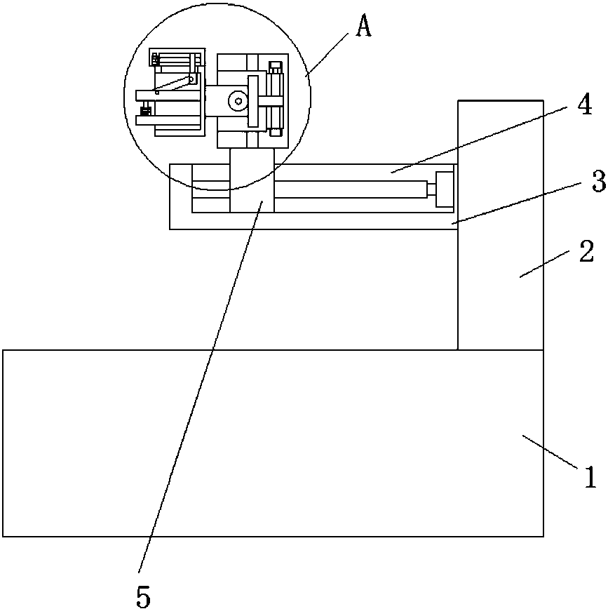
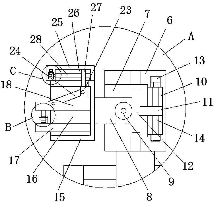
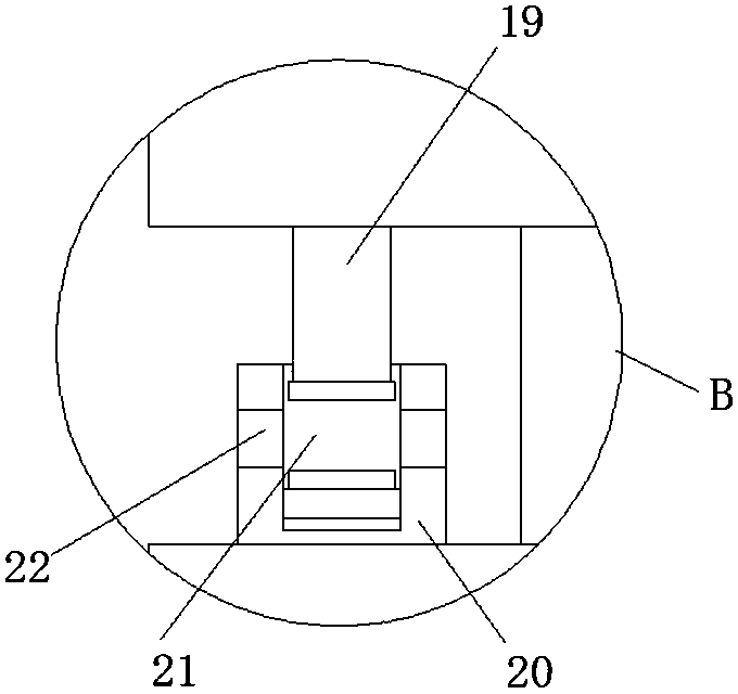
[0025] refer to Figure 1-5, in this embodiment, a shoe upper tensioning device for a shoe processing machine is proposed, comprising a base 1, a support plate 2 is fixedly installed on the top of the base 1, and a side of the support plate 2 is fixedly installed above the base 1. Seat 3, the top of the installation seat 3 is provided with a first installation slot 4, a mounting block 5 is slidably installed in the first installation slot 4, and a movable seat 6 is fixedly installed on the top of the installation block 5, and the movable seat 6 is driven by the installation block 5. Moving, the side of the moving base 6 away from the support plate 2 is provided with a rotating groove 7, and a rotating block 8 is rotated and installed in the rotating groove 7. The side of the rotating block 8 away from the support plate 2 extends to the outside of the moving base 6 and is fixedly installed The fixed table 15 is driven by the rotating block 8 to rotate. The inner wall of the rot...


PUM


Abstract

The invention discloses an upper tensioner of a shoe machine. The upper tensioner comprises a base. A support plate is fixedly mounted at the top of the base. A mounting base, located above the base,is fixedly mounted on one side of the support plate. A first mounting groove is formed in the top of the mounting base. A mounting block is mounted in the first mounting groove slidably. A moving baseis mounted at the top of the mounting block fixedly. A rotating groove is formed in one side, away from the support plate, of the moving base. A rotating block is mounted in the rotating groove rotationally. One side, away from the support plate, of the rotating block extends to the outer side of the moving base, and a fixed platform is fixedly mounted on the side. A first moving groove is formedin the inner wall, away from an opening of the rotating groove, of the rotating groove. The upper tensioner has the advantages that upper grabbing threads are clamped and fixed conveniently, stability of the upper grabbing threads during tensioning is enhanced, the tensioning angle is adjusted conveniently, and accordingly, the upper grabbing threads are tensioned at a proper angle; the upper tensioner is simple in structure and convenient to use.

Description

technical field [0001] The invention relates to the technical field of shoe processing, in particular to a shoe upper tensioning device for a shoe processing machine. Background technique [0002] Shoes are an indispensable item in people's daily life. Shoe-making has the characteristics of complex processes and high technical requirements, so most of the processes are still manual operations. Taking running shoes as an example, the upper and sole are first made separately, and then the upper is made. Set on the shoe last, carry out the grasping operation, and finally spray glue and cover the bottom. In the upper grasping process, the upper needs to be tightened and stretched to remove or reduce wrinkles, so as to achieve the purpose of sticking the last, thereby Improve the aesthetics of your shoes. [0003] After searching, the patent document with the application publication number CN106880131A discloses a device for pulling and grasping the upper thread, which solves th...

Claims


Application Information

Patent Timeline
Patent Type & Authority Applications(China)
IPC IPC(8): A43D9/00
CPCA43D9/00
Inventor 庄英才
Owner 石狮市高鑫技术孵化有限公司
Why Eureka
Try Eureka