Machine tool integrating snap spring groove cutting, end face turning, chamfering and central hole punching of roller carrier shaft

A technology for punching center holes and idler shafts, which is applied to metal processing machinery parts, other manufacturing equipment/tools, metal processing, etc., can solve the problems of reducing processing efficiency, reducing labor efficiency, and low feeding efficiency, so as to improve processing efficiency , save manpower, material resources and time, and improve efficiency

Active Publication Date: 2018-08-10
FUZHOU SANXUN MACHINERY
View PDF7 Cites 14 Cited by
  • Summary
  • Abstract
  • Description
  • Claims
  • Application Information

AI Technical Summary

Problems solved by technology

[0005] 1. During the machining process of CNC machine tools, operators need to wait beside the CNC machine tools all the time to match the production rhythm of CNC machine tools, resulting in high labor costs and low feeding efficiency;
[0006] 2. Unnecessary work-related accidents may occur due to a slight carelessness of the operator, which poses a great safety hazard;
[0007] 3. Since one machine tool can only realize one function, multiple machine tools need to be placed in the process of processing, which will occupy a large area. Each machine tool needs at least one operator to control and reduce the Labor efficiency, which greatly improves labor costs and reduces processing efficiency

Method used


Image

  • Machine tool integrating snap spring groove cutting, end face turning, chamfering and central hole punching of roller carrier shaft
  • Machine tool integrating snap spring groove cutting, end face turning, chamfering and central hole punching of roller carrier shaft
  • Machine tool integrating snap spring groove cutting, end face turning, chamfering and central hole punching of roller carrier shaft

Examples


Embodiment Construction

[0051] In order to make the present invention more comprehensible, a preferred embodiment is now described in detail with accompanying drawings as follows.

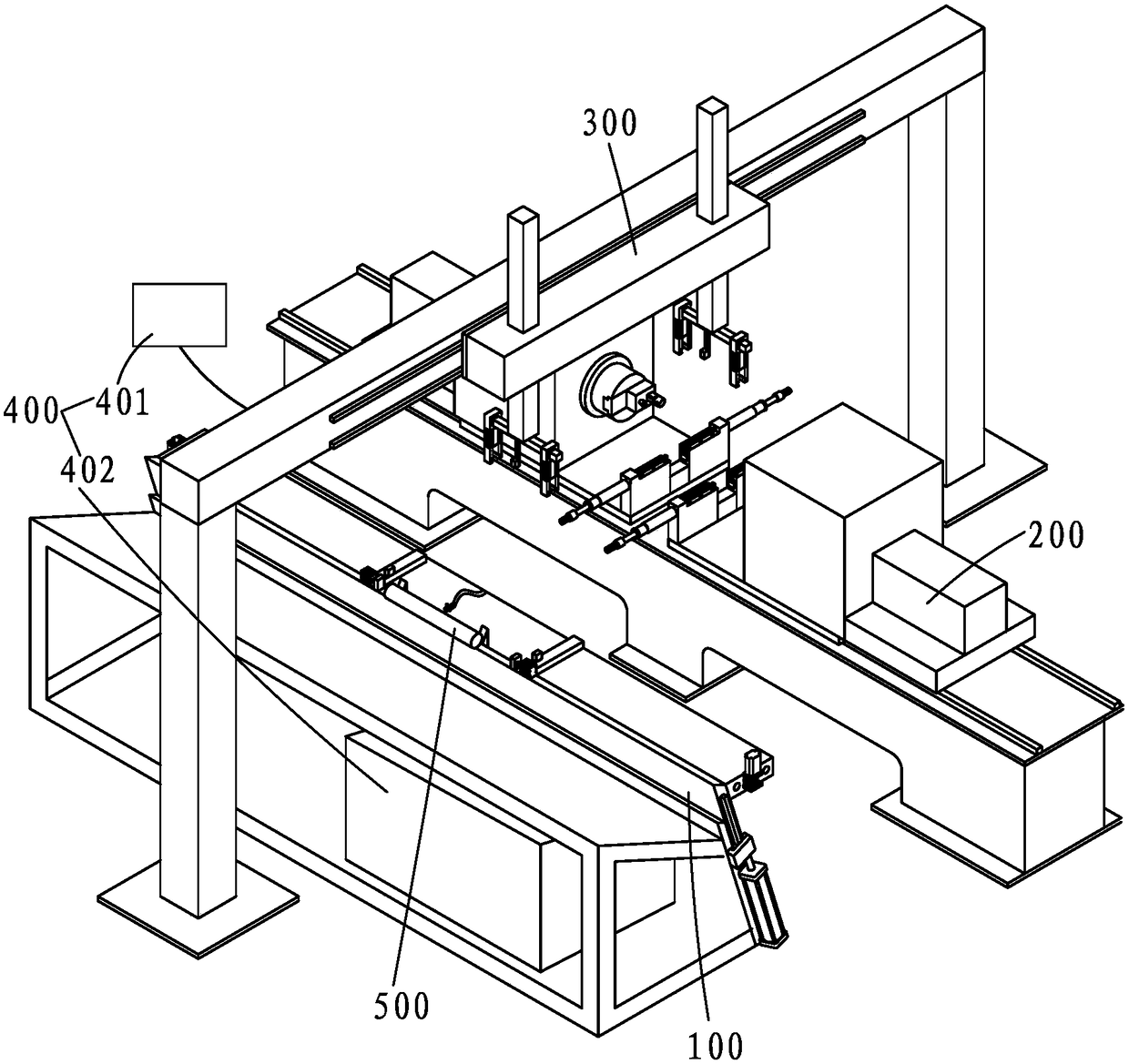
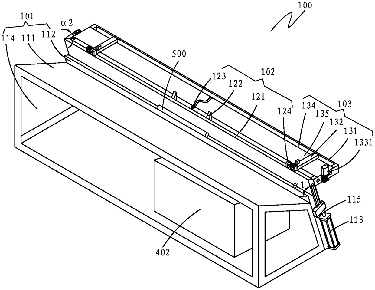
[0052] Such as figure 1 As shown, a machine tool of the present invention that integrates the cutting of the circlip groove, the end face of the car, the chamfering and the punching of the center hole includes an automatic feeding mechanism 100, a processing mechanism 200 for the roller shaft, and an automatic grabbing mechanism 300. And a control mechanism 400, the roller shaft processing mechanism 200 includes a processing platform 201, a workpiece placement table 202, two sets of main linear guide rails 203, two idler shaft processing devices 204, two main ball screws 205, two main Screw nut 206 and two main servo motors (not shown), one set of main linear guide rails 203 is relatively arranged on the left end of processing platform 201, and another group of said main linear guide rails 203 is relatively arranged on th...


PUM


Abstract

The invention provides a machine tool integrating snap spring groove cutting, end face turning, chamfering and central hole punching of a roller carrier shaft. The machine tool comprises an automaticfeeding mechanism, a roller carrier shaft machining mechanism, an automatic material grabbing mechanism and a control mechanism. The roller carrier shaft machining mechanism comprises a machining platform, a workpiece placement platform, main linear guide rails, a roller carrier shaft machining device, a main ball screw and a main servo motor. The main linear guide rails are arranged at the end ofthe machining platform oppositely. The workpiece placement platform is arranged between the main linear guide rails. The roller carrier shaft machining device is installed on the main linear guide rails. The two sides of the main ball screw are fixed to the main servo motor and the machining platform respectively. The middle of the main ball screw is fixed to the roller carrier shaft machining device. The operation end of the roller carrier shaft machining device is flush with an arrangement port of the workpiece placement platform according to the height. The arrangement port and a placementport are arranged oppositely. Two mechanical arms of the automatic material grabbing mechanism are arranged above the arrangement port and the placement port respectively. The control mechanism is connected with the automatic feeding mechanism, the main servo motor, the roller carrier shaft machining device and the automatic material grabbing mechanism. With the machine tool integrating snap spring groove cutting, end face turning, chamfering and central hole punching of the roller carrier shaft, the machining efficiency is improved.

Description

technical field [0001] The invention relates to the technical field of machinery, in particular to a machine tool for cutting a spring groove, turning an end face, chamfering and punching a center hole for an idler shaft. Background technique [0002] The idler shaft is an important part of the belt conveyor. Its main function is to hold up the conveyor belt and the materials on the conveyor belt on the one hand, and to use the friction between it and the conveyor belt to drive the idler tube and the bearing. Seat, bearing outer ring and seals make rotary motion, so as to realize material transmission together with the conveyor belt. [0003] At present, CNC machine tools are generally loaded and unloaded manually by the operator. After each surface of the workpiece is processed, the operator manually replaces the other surface and re-clamps, and then starts the CNC machine tool processing. Each workpiece must be manually clamped many times; and, traditionally The processin...

Claims


Application Information

Patent Timeline
Patent Type & Authority Applications(China)
IPC IPC(8): B23P23/04B23Q7/04B23Q7/00B23Q5/40
CPCB23P23/04B23Q5/40B23Q7/00B23Q7/04
Inventor 林东
Owner FUZHOU SANXUN MACHINERY
Why Eureka
Try Eureka