A self-feeding automatic grinding machine for round rods
What is AI technical title?
AI technical title is built by Patsnap AI team. It summarizes the technical point description of the patent document.
A grinding machine and self-feeding technology, which is applied in the direction of grinding racks, grinding machine parts, grinding machines, etc., can solve the problems of uneven distribution of force on the grinding contact surface, high labor intensity, and high quality requirements, so as to reduce labor costs. Labor intensity, improve work efficiency, small size effect
Active Publication Date: 2021-02-19
WUHU LANREN INTELLIGENT TECH
View PDF12 Cites 0 Cited by
Summary
Abstract
Description
Claims
Application Information
AI Technical Summary
This helps you quickly interpret patents by identifying the three key elements:
Problems solved by technology
Method used
Benefits of technology
Problems solved by technology
[0002] As an important part of automobile assembly, the production and processing of parts and components requires large batches and high quality requirements. Among them, round rod workpieces are widely used in automobiles and are often used as reinforced protection parts, such as bumpers; support parts, For example, the connecting rod of the frame and the round bar workpiece need to be polished to remove the surface oxide layer or rust layer before processing. In the prior art, the round bar workpiece is mostly manually grabbed and loaded, and the labor intensity is high for long-term work. , Low efficiency, and sandpaper or emery cloth is mostly used for grinding round rods, the force distribution on the grinding contact surface is uneven, and excessive grinding is prone to occur
Method used
Image
Click on the blue label to locate the original text in one second.
Reading with bidirectional positioning of images and text.
Examples
Embodiment Construction
[0028] In order to make the technical means, creative features, goals and effects achieved by the present invention easy to understand, the present invention will be further elaborated below.
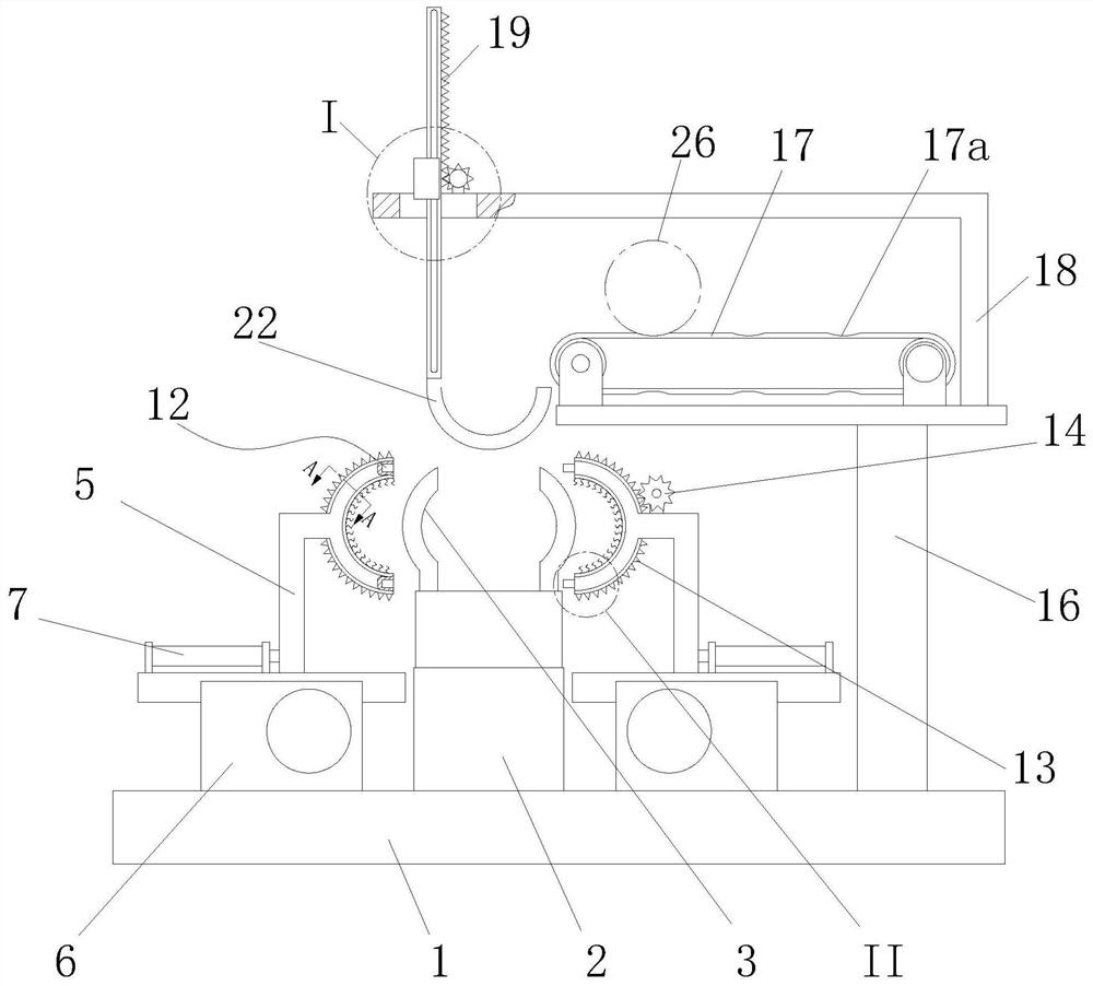
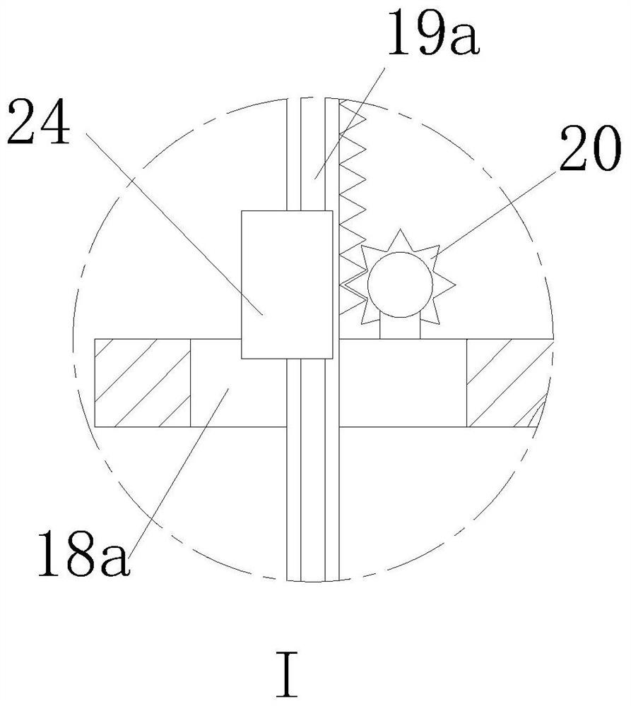
[0029] like Figure 1 to Figure 7 As shown, a self-feeding type automatic grinding machine for round rods includes a base 1, a mounting base 2 is fixed on the base 1 and a hydraulic gripper 3 is connected to the mounting base 2, and a hydraulic gripper 3 is connected to the mounting base 2. It is equipped with a feeding mechanism that cooperates with the hydraulic gripper 3 and realizes the sequential output of the round rods 26, and two symmetrically arranged combined mobile grinding mechanisms that are respectively located on the left and right sides of the mounting base 2.
[0030] Described round bar feeding mechanism comprises T-shaped mounting base 16, the conveyer belt 17 that is installed on the T-shaped mounting base 16, the support block 18 that is fixed on the left end of T-s...
PUM
Abstract
The invention relates to a self-feeding type automatic grinding machine for round rods, comprising a base, on which a mounting seat is fixed and a hydraulic gripper is connected to the mounting seat, and the mounting seat is equipped with a hydraulic gripper to cooperate with and realize The feeding mechanism for round rods output sequentially, and two combined mobile grinding mechanisms that are located on the left and right sides of the mounting seat and are symmetrically arranged; the round rod feeding mechanism includes a T-shaped mounting seat, a conveyor belt, a support block, a long Rack, No. 2 motor, pinion, rotating motor, steering block, C-shaped pick-up plate; the mobile grinding mechanism includes a grinding block, an L-shaped moving seat, a base, a driving cylinder, a lead screw, and a driving motor. There are teeth, and the L-shaped mobile seat positioned on the right side is provided with a driving gear, and the driving gear is connected with a No. 1 motor. The invention can realize the mechanized feeding of the round bar grinding, reduce the labor intensity, improve the working efficiency, the round bar is evenly stressed, avoids excessive grinding, and is small in size and easy to operate.
Description
technical field [0001] The invention relates to the technical field of production and processing of auto parts, in particular to a self-feeding automatic grinding machine for round bars. Background technique [0002] As an important part of automobile assembly, the production and processing of parts and components requires large batches and high quality requirements. Among them, round rod workpieces are widely used in automobiles and are often used as reinforced protection parts, such as bumpers; support parts, For example, the connecting rod of the frame and the round bar workpiece need to be polished to remove the surface oxide layer or rust layer before processing. In the prior art, the round bar workpiece is mostly manually grabbed and loaded, and the labor intensity is high for long-term work. , The efficiency is low, and sandpaper or emery cloth is mostly used for grinding the round rod, the force distribution of the grinding contact surface is uneven, and excessive gr...
Claims
Application Information
Patent Timeline
Application Date:The date an application was filed.
Publication Date:The date a patent or application was officially published.
First Publication Date:The earliest publication date of a patent with the same application number.
Issue Date:Publication date of the patent grant document.
PCT Entry Date:The Entry date of PCT National Phase.
Estimated Expiry Date:The statutory expiry date of a patent right according to the Patent Law, and it is the longest term of protection that the patent right can achieve without the termination of the patent right due to other reasons(Term extension factor has been taken into account ).
Invalid Date:Actual expiry date is based on effective date or publication date of legal transaction data of invalid patent.

