Swing grinding equipment

A swing-type, equipment technology, applied in the direction of grinding/polishing equipment, mechanical equipment, metal processing equipment, etc., can solve the problems of lack of real-time tensioning and adjustment of the abrasive belt, abrasive belt detachment, unqualified workpiece grinding quality, etc., to achieve Improve space utilization, uniform grinding force, and improve the effect of grinding quality

Pending Publication Date: 2020-07-03
浙江希尔机器人股份有限公司
View PDF0 Cites 4 Cited by
  • Summary
  • Abstract
  • Description
  • Claims
  • Application Information

AI Technical Summary

Problems solved by technology

[0002] At present, the existing grinding equipment is a translational abrasive belt grinding equipment, and the abrasive belt grinding surface is a whole straight line, which does not allow the abrasive belt to form a certain angle. There are some positions that cannot be polished for parts with complex shapes. Moreover, the existing abrasive belt grinding equipment lacks the functi

Method used


Image

  • Swing grinding equipment
  • Swing grinding equipment
  • Swing grinding equipment

Examples


Example Embodiment

[0030] The technical solution of the present invention will be further described in detail below in conjunction with the accompanying drawings of the specification.

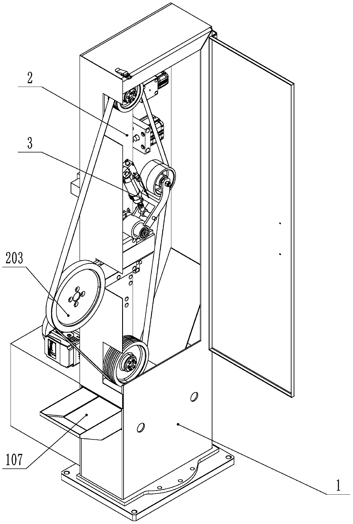
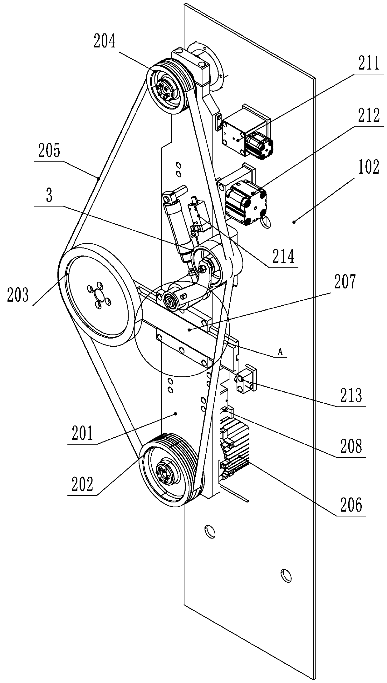
[0031] Such as Figure 1-2 As shown, a swing-type polishing equipment includes an equipment frame 1 and an abrasive belt polishing mechanism 2 provided on the equipment frame 1. The close operation side of the abrasive belt polishing mechanism 2 is the front side, and the far side is the rear side The equipment rack 1 includes a rack base 101 and a rack mounting plate 102. The abrasive belt grinding mechanism 2 includes a swing seat plate 201, a driving wheel 202, a driven wheel 203, a fixed wheel 204 and an abrasive belt 205. The driving wheel 202 is fixed by connection The grinding motor 206 on the swing seat plate 201 is connected and driven. The driven wheel 203 is connected to the swing seat plate 201 through a position adjustment mechanism 207 that can adjust the front and rear positions of the driven wheel 203...


PUM


Abstract

The invention discloses swing grinding equipment, and relates to the field of part grinding equipment. Existing abrasive belt grinding equipment is translation equipment, and positions which cannot beground exist when parts complex in appearance are ground. The swing grinding equipment comprises an equipment rack, an abrasive belt grinding mechanism and an abrasive belt automatic tensioning adjusting mechanism, wherein the abrasive belt grinding mechanism comprises a swing seat plate, a driving wheel, a driven wheel, a fixed wheel and an abrasive belt, and the fixed wheel and the swing seat plate are rotationally connected with a rack mounting plate so that the end, located on the fixed wheel, of the swing seat plate can rotate around a shaft; and the fixed wheel and the driving wheel arelocated at the upper end and the lower end of the swing seat plate respectively, the swing seat plate is connected with the rack mounting plate through a guide sliding assembly, and a buffer used forbuffering rotary swing of the swing seat plate is arranged on the equipment rack. By means of stress swing of the swing seat plate during workpiece grinding and a certain inclination angle formed bythe abrasive belt through the driven wheel, grinding stress is more uniform, the parts complex in appearance can be better ground in place, and the workpiece grinding quality can be improved.

Description

technical field [0001] The invention relates to the field of parts grinding equipment, in particular to a swing grinding equipment. Background technique [0002] At present, the existing grinding equipment is a translational abrasive belt grinding equipment, and the abrasive belt grinding surface is a whole straight line, which does not allow the abrasive belt to form a certain angle. There are some positions that cannot be polished for parts with complex shapes. Moreover, the existing abrasive belt grinding equipment lacks the function of automatic real-time tensioning and adjustment of the abrasive belt. After the equipment has been used for a period of time, the quality of the workpiece grinding will be unqualified or the abrasive belt will be separated from the equipment in severe cases. Some grinding equipment and processes are redeveloped and designed to solve the deficiencies of the existing technology. Contents of the invention [0003] The technical problem to be...

Claims


Application Information

Patent Timeline
IPC IPC(8): B24B21/00B24B21/18B24B21/20B24B49/00F16F15/023
CPCB24B21/00B24B21/18B24B21/20B24B41/007B24B49/00F16F15/023
Inventor 张立富高杰张远矩
Owner 浙江希尔机器人股份有限公司
Why Eureka
Try Eureka