Passive manipulator

A manipulator and manipulator technology, applied in the field of passive manipulators, can solve the problems of complex manipulator structure, high manipulator cost, and large volume, and achieve the effect of simple and compact overall structure, high explosion-proof safety, and small size.

Pending Publication Date: 2018-08-10
HENGYANG LIMEI BATTERY VEHICLES MFG CO LTD
View PDF16 Cites 3 Cited by
  • Summary
  • Abstract
  • Description
  • Claims
  • Application Information

AI Technical Summary

Problems solved by technology

[0004] In general, whether electric power or compressed gas or liquid is used to drive the movement of the jaws, it is necessary to equip the jaws of the manipulator with a drive mechanism with a

Method used


Image

  • Passive manipulator
  • Passive manipulator
  • Passive manipulator

Examples


Embodiment Construction

[0049] In order to facilitate the understanding of those skilled in the art, the present invention will be further described below in conjunction with the embodiments and accompanying drawings, and the contents mentioned in the embodiments are not intended to limit the present invention.

[0050] It should be noted in advance that in the present invention, unless otherwise specified and limited, the terms "installation", "connection", "connection", "fixation" and other terms should be understood in a broad sense, for example, it can be a fixed connection, It can also be detachably connected or integrally connected; it can be directly connected or indirectly connected through an intermediary, and it can be internal communication between two components. Those of ordinary skill in the art can understand the specific meanings of the above terms in the present invention according to specific situations.

[0051] In addition, in the present invention, unless otherwise clearly specifie...


PUM


Abstract

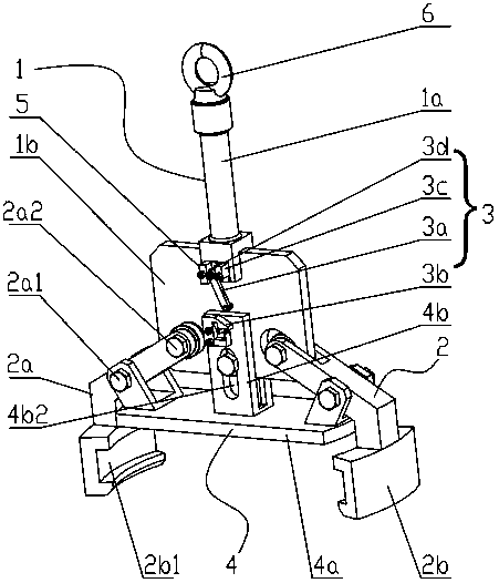
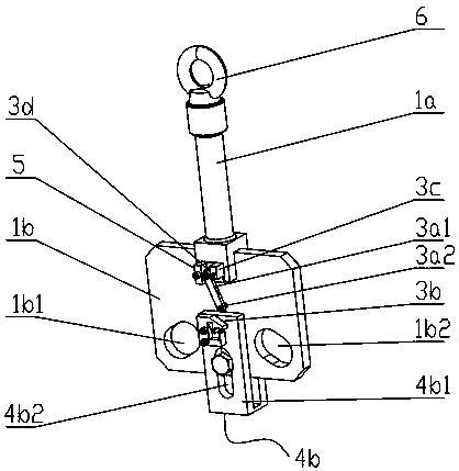
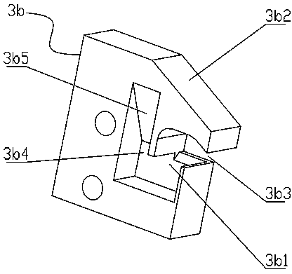
The invention relates to a passive manipulator. The passive manipulator comprises a mechanical arm, at least two clamping jaws, a clamping jaw locking mechanism and a clamping jaw seat positioned below the mechanical arm, wherein each clamping jaw comprises a clamping rod and a clamping head connected to the front end of the clamping rod. The clamping jaw seat is movably connected with the mechanical arm and can move up and down relative to the mechanical arm, the clamping rod is provided with a first connecting point and a second connecting point, the first connecting point is positioned between the clamping head and the second connecting point, the first connecting point is hinged on the clamping jaw seat, and the second connecting point is movably connected with the mechanical arm. Theclamping jaw locking mechanism comprises a locking hook and a guiding and locking structure, wherein the locking hook, the guiding and locking structure are separately arranged on the clamping jaw seat and the mechanical arm, the guiding and locking structure comprises a locking groove and a guiding structure for guiding the locking hook to move into the locking groove and to disengage from the locking groove, and the clamping jaws do not need a driving mechanism with a power source to drive when carrying out clamping and loosening actions, the passive manipulator is compact in overall structure, small in volume, low in cost, and has high explosion-proof safety.

Description

technical field [0001] The invention relates to the technical field of automation equipment, in particular to a passive manipulator. Background technique [0002] In order to pursue higher production efficiency, more and more occasions have begun to use manipulators to replace the original manual work, such as item transfer work. Most of the existing item transfer manipulators use active manipulators, that is, such manipulators need to be connected to the power source. The driving mechanism is used to drive the movement of the jaws (the opening and closing of the jaws does not require a manipulator driven by a power source, called a passive manipulator), so as to realize the clamping and loosening of the item. [0003] For a manipulator that relies on electric power to drive the gripper, if it is to be applied to the grasping of flammable and explosive items, it is necessary to design an explosion-proof design for the electrical part to prevent the electric sparks generated ...

Claims


Application Information

Patent Timeline
IPC IPC(8): B25J15/08
CPCB25J15/08Y02E30/30
Inventor 王勤黄忠良
Owner HENGYANG LIMEI BATTERY VEHICLES MFG CO LTD
Why Eureka
Try Eureka