Forming mold for aerospace bracket

A technology for aerospace and forming molds, applied in household appliances, other household appliances, applications, etc., can solve the problems of mold docking, unsafe planes, waste of time, etc., to improve work efficiency, convenient and fast docking operations, and correct deviation. Effect

Active Publication Date: 2020-07-17
倪惠芳
View PDF1 Cites 1 Cited by
  • Summary
  • Abstract
  • Description
  • Claims
  • Application Information

AI Technical Summary

Problems solved by technology

[0002] When the aerospace support is in use, the connecting holes on both sides of the hollow cylinder need to be riveted to the aircraft with rivets. When riveting, the two connecting holes need to be riveted with interference. Since the side expansion force is particularly large during riveting, the strength of the holes The requirements are relatively high, and no weld marks of any kind can appear on the outer wall of the hole. Otherwise, the sides of the two connecting holes are easily cracked, which brings great unsafe factors to the aircraft. For example, the patent application number 201220280361.2 includes a fixed mold Seat plate, fixed formwork, movable formwork, square iron and movable formwork seat plate, the fixed formwork seat plate and the movable formwork seat plate are set up and down, and inlet gates are respectively set at the two ends of the required forming support, and the described inlet The gate is tangent to the outer circle at both ends of the support, the gate is connected to the gate sleeve, the gate sleeve is fixed on the upper part of the fixed mold seat plate, and the gate sleeve is connected to the nozzle of the injection machine, although To a certain extent, the strength of the connection hole on the bracket is increased, but its mold is very troublesome when docking, which brings a lot of inconvenience to production and wastes time

Method used


Image

  • Forming mold for aerospace bracket
  • Forming mold for aerospace bracket
  • Forming mold for aerospace bracket

Examples


Embodiment Construction

[0015] The following will clearly and completely describe the technical solutions in the embodiments of the present invention with reference to the accompanying drawings in the embodiments of the present invention. Obviously, the described embodiments are only some, not all, embodiments of the present invention. Based on the embodiments of the present invention, all other embodiments obtained by persons of ordinary skill in the art without making creative efforts belong to the protection scope of the present invention.

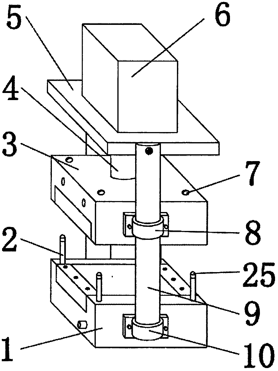
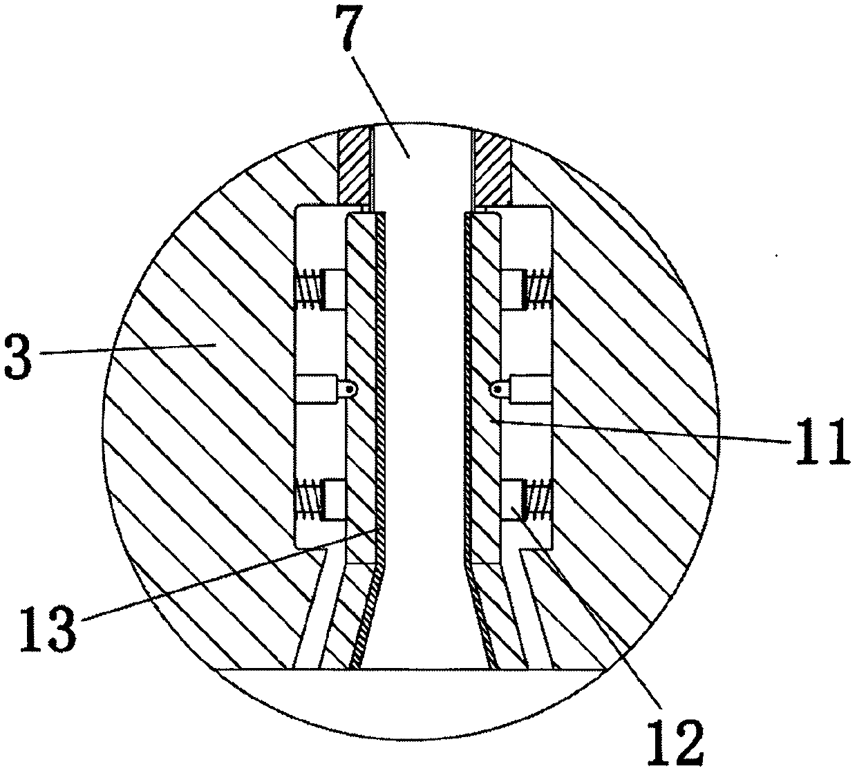
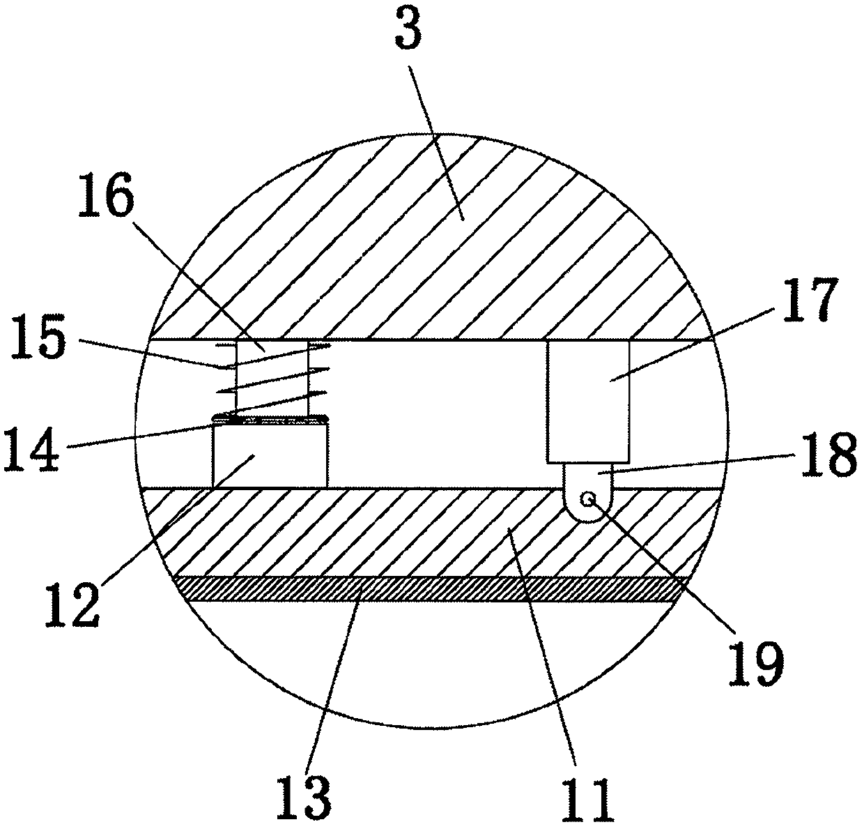
[0016] see Figure 1-4 , the present invention provides a kind of technical scheme: a kind of forming mold of aerospace support, comprises fixed mold frame 1, and fixed mold frame 1 is used for installing and fixing the lower mold, and the top four corners of top mold frame 1 are equipped with guide rods 2, The top of the guide rod 2 is equipped with a metal head 25, the metal head 25 is made of smooth and circular metal, and is used to reduce the friction for...


PUM


Abstract

The invention discloses a forming mould of a bracket for aerospace. The forming mould comprises a fixed mould frame, and four corners of the top end of the fixed mould frame are each provided with a guide rod; the front and rear sides of the fixed mould frame are each provided with a support column connected to the fixed mould frame through a supporting ring, and a movable mould frame is installedbetween the support columns, and connected to the fixed mould frame in a lap joint manner; the movable mould frame is connected to the support columns through lantern rings, and the lantern rings areconnected to the support columns in the lap joint manner. According to the forming mould of the bracket for aerospace, during forming of the bracket, a hydraulic pump is controlled by a hydraulic machine to drive a push rod to move, and the movable mould frame is driven by the push rod to move; the bottom end of a guide hole is provided with an open guide pipe so that the guide rod easily entersthe guide hole; the guide rod is led into the deep position of the guide hole through the open guide pipe, so that the deviation of butt joint between the movable mould frame and the fixed mould frameis corrected effectively, and the butt joint operation between the movable mould frame and the fixed mould frame is convenient, efficient, and time and labor-saving; and thus, the working efficiencyis improved effectively.

Description

technical field [0001] The invention relates to the technical field of mold equipment, in particular to a molding mold for an aerospace bracket. Background technique [0002] When the aerospace support is in use, the connecting holes on both sides of the hollow cylinder need to be riveted to the aircraft with rivets. When riveting, the two connecting holes need to be riveted with interference. Since the side expansion force is particularly large during riveting, the strength of the holes The requirements are relatively high, and no weld marks of any kind can appear on the outer wall of the hole. Otherwise, the sides of the two connecting holes are easily cracked, which brings great unsafe factors to the aircraft. For example, the patent application number 201220280361.2 includes a fixed mold Seat plate, fixed formwork, movable formwork, square iron and movable formwork seat plate, the fixed formwork seat plate and the movable formwork seat plate are set up and down, and inle...

Claims


Application Information

Patent Timeline
Patent Type & Authority Patents(China)
IPC IPC(8): B29C45/26B29C45/67B29L31/30
CPCB29C45/2606B29C45/67B29L2031/3076
Inventor 倪惠芳
Owner 倪惠芳
Why Eureka
Try Eureka