Vertical take-off and landing plant protection unmanned aerial vehicle structure

A technology for planting and securing drones and vertical take-off and landing, applied in the field of drones, can solve the problems of long take-off and landing distance, high environmental requirements for take-off and landing, and inability to take off and land at any time, and achieve the effect of low standby energy consumption

Pending Publication Date: 2018-08-10
扬州市东马无人机科技有限公司
View PDF0 Cites 0 Cited by
  • Summary
  • Abstract
  • Description
  • Claims
  • Application Information

AI Technical Summary

Problems solved by technology

[0002] Common fixed-wing aircraft in the aviation field mainly rely on the wings to generate lift to balance the weight of the aircraft. At the same time, the power rotor enables the aircraft to overcome air resistance and fly. However, the traditional fixed-wing aircraft has a long take-off and landing distance, which requires environmental requirements Higher, unable to take off and land at any time; at the same time, because of the fixing method of the rotor, the rotor-type helicopter multi-axis aircraft only has advantages in climbing heights, while long-distance high-speed flight and flexible steering appear to be relatively lacking

Method used


Image

  • Vertical take-off and landing plant protection unmanned aerial vehicle structure
  • Vertical take-off and landing plant protection unmanned aerial vehicle structure
  • Vertical take-off and landing plant protection unmanned aerial vehicle structure

Examples


Embodiment Construction

[0025] The present invention is described in further detail now in conjunction with accompanying drawing. These drawings are all simplified schematic diagrams, which only illustrate the basic structure of the present invention in a schematic manner, so they only show the configurations related to the present invention.

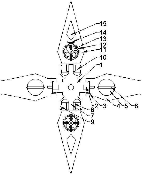
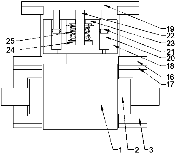
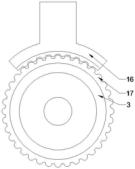
[0026] like Figure 1~3 As shown, the present invention is a vertical take-off and landing plant protection unmanned aerial vehicle structure, including a connection platform, a set of balance wings are respectively arranged on the lateral sides of the connection platform, and a group of forwarding wings are respectively provided on the longitudinal sides of the connection platform. wing; the balance wing comprises a balance wing body and a balance wing base, wherein a group of stepper motors A are respectively arranged on both lateral sides of the connecting platform, and the balance wing base is fixed on the rotating shaft of the stepper motor A, so The end...


PUM


Abstract

The invention relates to a vertical take-off and landing plant protection unmanned aerial vehicle structure. The structure comprises a connecting table. A balancing wing is arranged on each of the twotransverse sides of the connecting table. An advancing wing is arranged on each of the two longitudinal sides of the connecting table. Each balancing wing comprises a balancing wing body and a balancing wing base. A stepping motor A is arranged on each of the two transverse sides of the connecting table. The balancing wing bases are fixed to rotary shafts of the stepping motors A. The ends of thebalancing wing bases and the side walls of the connecting table are rotationally connected. The balancing wing bodies are fixed to the balancing wing bases. Drive fans A are perpendicularly arrangedon the middle portions of the balancing wing bodies. Each advancing wing comprises an advancing wing base and an advancing wing body. A fixing seat is arranged on each of the two longitudinal sides ofthe connecting table. Stepping motors B are arranged on the fixing seats. The rotation axes of the stepping motors B and the transverse axis of the connecting table are coaxial. The advancing wing bases are connected to rotary shafts of the stepping motors B. Drive fans B are arranged on the advancing wings. Anti-deflection wings are further perpendicularly arranged on the middle portions of theadvancing wings.

Description

technical field [0001] The invention relates to a vertical take-off and landing plant protection unmanned aerial vehicle structure, which belongs to the field of unmanned aerial vehicles. Background technique [0002] Common fixed-wing aircraft in the aviation field mainly rely on the wings to generate lift to balance the weight of the aircraft. At the same time, the power rotor enables the aircraft to overcome air resistance and fly. However, the traditional fixed-wing aircraft has a long take-off and landing distance, which requires environmental requirements Higher, unable to take off and land at any time; at the same time, because of the fixing method of the rotor, the rotor-type helicopter multi-axis aircraft only has advantages in climbing heights, while long-distance high-speed flight and flexible steering appear to be relatively lacking. Contents of the invention [0003] The technical problem to be solved by the present invention is to overcome the technical prob...

Claims


Application Information

Patent Timeline
Patent Type & Authority Applications(China)
IPC IPC(8): B64C29/00
CPCB64C29/0033B64U10/13B64U30/20B64U50/14
Inventor 马晓光冯波涛孙红军
Owner 扬州市东马无人机科技有限公司
Why Eureka
Try Eureka