A self-priming starting device applied to a centrifugal pump

A technology of starting device and centrifugal pump, which is applied to the components, pump, driving pump, etc. of pumping device for elastic fluid, can solve the problems of long start-up period, damage of hydraulic components, lower self-priming efficiency, etc., so as to improve occupancy Large space, reduce vibration and noise, improve self-priming efficiency

Active Publication Date: 2020-09-25
JIANGSU UNIV
View PDF18 Cites 0 Cited by
  • Summary
  • Abstract
  • Description
  • Claims
  • Application Information

AI Technical Summary

Problems solved by technology

However, the centrifugal pumps currently on the market need to fill the pump cavity with water before each start. The operation is complicated, the workload is heavy, the start-up period is long, and it is difficult to meet the requirements of rapid water delivery.
[0003] Although the self-priming centrifugal pump needs to be filled with water except for the first start-up, the subsequent start-up process can be carried out directly, but the structure of the self-priming centrifugal pump is complex, the internal flow field has a large turbulent energy loss, and the gas-liquid mixing and gas-liquid separation are uniform. Occurred inside the pump cavity, it will cause damage to the internal hydraulic components, and it is very difficult to replace and repair
At the same time, during the self-priming start-up process, the gas-liquid separation process occurs inside the pump chamber, and it is easy to form gas nuclei inside the pump chamber, resulting in incomplete gas-liquid separation and reducing self-priming efficiency

Method used


Image

  • A self-priming starting device applied to a centrifugal pump

Examples


Embodiment Construction

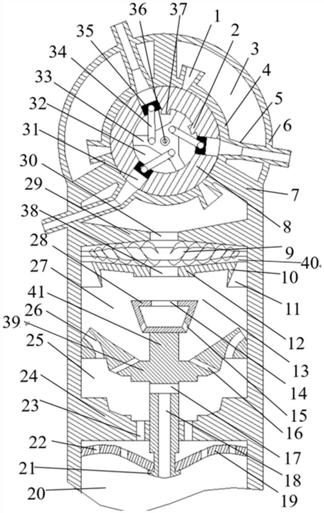
[0032] Embodiments of the present invention are described in detail below, examples of which are shown in the drawings, wherein the same or similar reference numerals designate the same or similar elements or elements having the same or similar functions throughout. The embodiments described below by referring to the figures are exemplary and are intended to explain the present invention and should not be construed as limiting the present invention.

[0033]In describing the present invention, it is to be understood that the terms "central", "longitudinal", "transverse", "length", "width", "thickness", "upper", "lower", "axial", The orientation or positional relationship indicated by "radial", "vertical", "horizontal", "inner", "outer", etc. is based on the orientation or positional relationship shown in the drawings, and is only for the convenience of describing the present invention and simplifying the description , rather than indicating or implying that the device or eleme...


PUM


Abstract

The invention provides a self-priming starting device applied to a centrifugal pump, which is installed on a water inlet pipe of the centrifugal pump and comprises an outer casing, an inner casing arranged in the outer casing from top to bottom, a first-stage baffle, a second-stage The partition plate, the opening and closing disc, the three-stage partition plate, and the elastic steel plate arranged in the water inlet pipe, the inner shell is provided with a drum, the inner shell is provided with an air intake pipe and an exhaust pipe, and the drum is provided with a drum inner cavity , There is a three-blade bracket in the drum, the three-blade bracket can drive the drum to rotate, a vertical rod is arranged on the opening and closing disc, a gas-liquid cutter is arranged between the first-level partition and the second-level partition, the first-level partition, the second-level partition The stage partition, the opening and closing disc and the tertiary partition are all provided with through holes, the bottom end of the vertical rod passes through the tertiary partition and the elastic steel plate, and the bottom end of the vertical rod is provided with a limit boss. The invention can effectively discharge the air in the pump chamber during the self-priming process, and can adjust the self-priming speed according to different pressures in the pump chamber, thereby realizing efficient gas-liquid separation and exhausting in the self-priming process.

Description

technical field [0001] The invention relates to a self-priming starting device, in particular to a self-priming starting device applied to a centrifugal pump. Background technique [0002] As an important fluid machine, centrifugal pumps are widely used in various conveying systems such as agriculture, industry, biology, and medical treatment. However, the centrifugal pumps currently on the market need to fill the pump cavity with water before starting each time. The operation is complicated, the workload is heavy, and the start-up period is long, which makes it difficult to meet the requirements of fast water delivery. [0003] Although the self-priming centrifugal pump needs to be filled with water except for the first start-up, the subsequent start-up process can be carried out directly, but the structure of the self-priming centrifugal pump is complex, the internal flow field has a large turbulent energy loss, and the gas-liquid mixing and gas-liquid separation are unifo...

Claims


Application Information

Patent Timeline
Patent Type & Authority Patents(China)
IPC IPC(8): F04D9/02F04D29/00
CPCF04D9/02F04D29/007F04D9/043F04D9/04F04B27/065F04D1/00
Inventor 李伟常浩施卫东周岭曹卫东朱勇郞涛魏洋洋
Owner JIANGSU UNIV
Why Eureka
Try Eureka