
Chemical self-priming pump

A self-priming pump, chemical technology, applied in the direction of pump, driving pump, non-variable-capacity pump, etc., can solve the problems of inconvenient backfilling and adding liquid, large loss of liquid kinetic energy, low self-priming performance, etc., to improve self-priming performance , The effect of improving self-priming efficiency and improving efficiency

Pending Publication Date: 2019-03-08
JIANGSU KAIQUAN PUMP IND MFG
View PDF8 Cites 0 Cited by
  • Summary
  • Abstract
  • Description
  • Claims
  • Application Information

AI Technical Summary

Problems solved by technology

[0003] Chemical self-priming pump refers to the vane pump used in the chemical industry. Compared with other types of pumps, it has the advantages of simple structure, not easy to wear, stable operation, low noise, uniform water outlet, convenient adjustment, high efficiency, corrosion resistance, It has the advantages of grinding and high temperature resistance; it can be used in the occasions where the container for storing liquid is 1-4 meters below the ground level, and it is inconvenient to pour back and add liquid; the pump can be fixed on the ground level post to continuously or intermittently extract and transport various chemical media , at present, there are defects in the structure of the chemical self-priming pump in the prior art, the gas-liquid separation in the pump chamber is poor, the loss of liquid kinetic energy is large, and the self-priming performance is low

Method used


Image

  • Chemical self-priming pump
  • Chemical self-priming pump

Examples


Embodiment Construction

[0016] The technical solutions of the present invention will be further described below in conjunction with the accompanying drawings and embodiments.

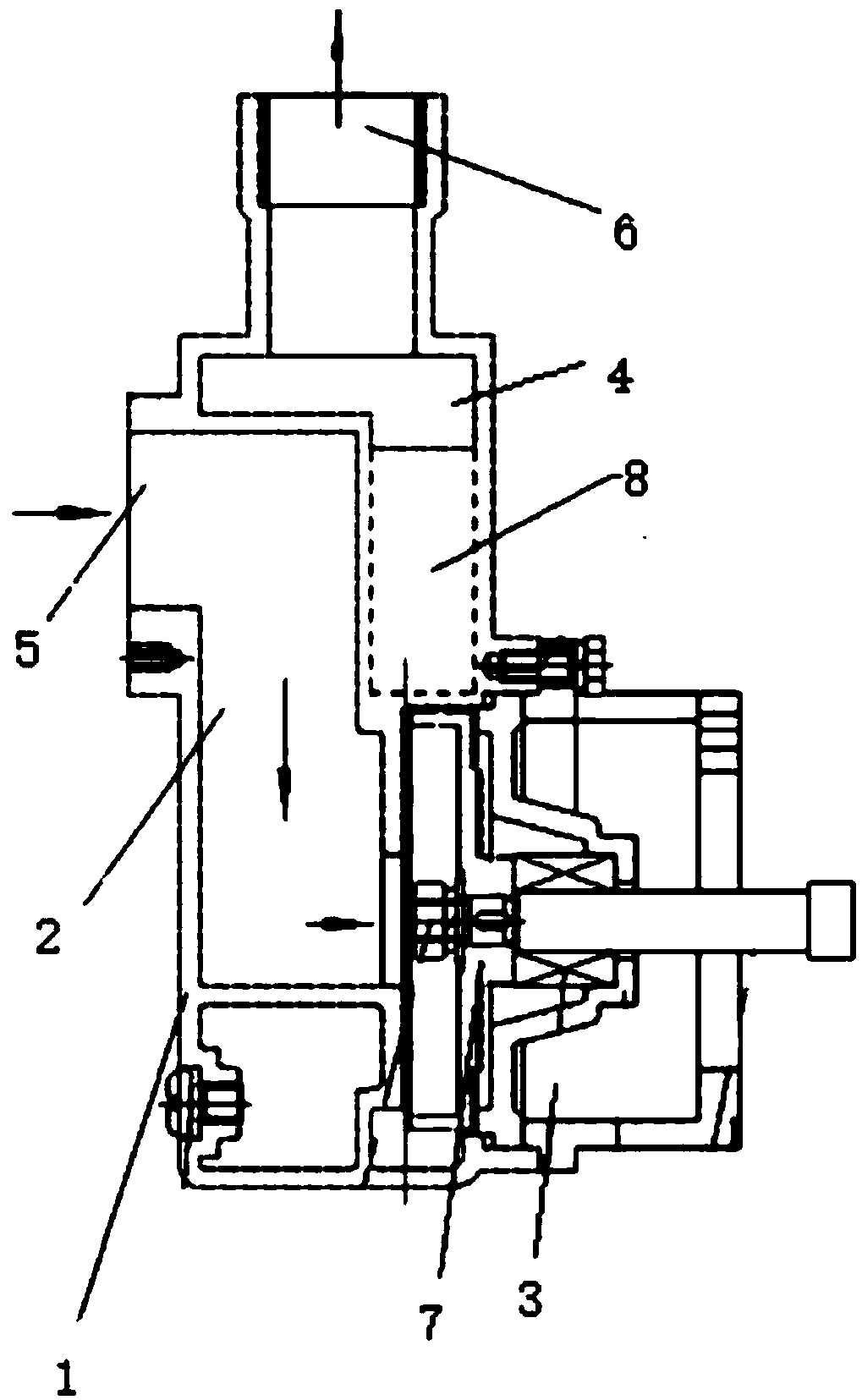
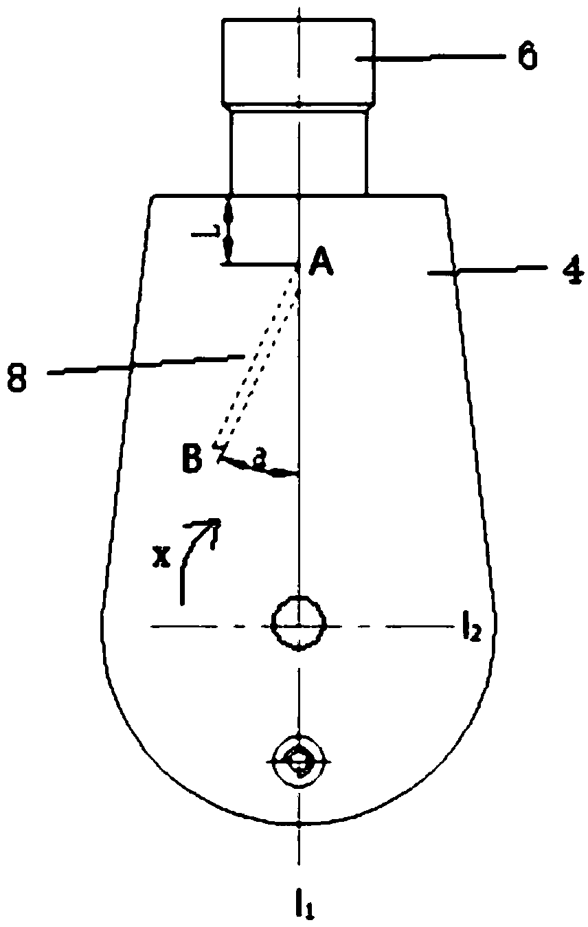
[0017] like figure 1 and figure 2 The shown chemical self-priming pump includes a pump body 1. A water inlet chamber 2, an impeller chamber 3, and a water outlet chamber 4 are arranged in the pump body 1. The water inlet chamber 2 communicates with the water outlet chamber 4 through the impeller chamber 3. A water inlet 5 is arranged on the water inlet chamber 2, a water outlet 6 is arranged on the water outlet chamber 4, an impeller 7 is arranged in the impeller chamber 3 facing the connection between the water inlet chamber 2 and the impeller chamber 3, and the water outlet chamber 4 The inside is located at the side of the water outlet of the impeller 7, and the partition plate 8 is arranged obliquely.

[0018] Both ends of the partition 8 are respectively fixed with the pump body 1 and cast integrally, and the partition...


PUM


Abstract

The invention discloses a chemical self-priming pump. The pump comprises a pump body, wherein a water inlet cavity, an impeller cavity and a water outlet cavity are arranged in the pump body, whereinthe water inlet cavity is communicated with the water outlet cavity through the impeller cavity, a water inlet is formed in the water inlet cavity, a water outlet is formed in the water outlet cavity,the impeller cavity is internally provided with an impeller which directly faces the communication part of the water inlet cavity and the impeller cavity, a partition plate is obliquely arranged inside the water outlet cavity and located on one side of the water outlet of the impeller. The pump has the advantages of being simple in structure, a reasonable partition plate structure is arranged inthe water outlet cavity, so that the steam-water separation speed of the self-priming pump in the self-suction starting stage is improved, the self-suction performance is improved, in the operation process, the partition plate eliminates the large vortex in the pump cavity, the volume loss is reduced, the efficiency of the self-priming pump is improved, and energy conservation and high efficiencyare achieved.

Description

technical field [0001] The invention relates to the technical field of water pumps, in particular to a chemical self-priming pump. Background technique [0002] The chemical industry occupies an important position in the national economy of various countries. It is the basic industry and pillar industry of many countries, including chemical industry, oil refining, metallurgy, energy, light industry, petrochemical, environment, medicine, environmental protection and military industry. Industries related to daily chemicals, energy and power, technology development, production technology management and scientific research. The development speed and scale of the chemical industry have a direct impact on all sectors of the social economy, and the world's annual output value of chemical products has exceeded 1.5 trillion US dollars. The chemical industry is a major polluter due to its wide variety, complex processes, and diverse products. At the same time, chemical products may ...

Claims


Application Information

Patent Timeline
Patent Type & Authority Applications(China)
IPC IPC(8): F04D9/02F04D9/00
CPCF04D9/00F04D9/02
Inventor 俞言芳
Owner JIANGSU KAIQUAN PUMP IND MFG
Learn More