Cooking range tossing flame guide structure and flame guide device

A stove and pot-turning technology, which is applied in the field of stove pot-turning flame-guiding structure and flame-guiding device, to achieve the effect of overcoming pressure adaptation damage

Active Publication Date: 2019-07-09
张跃虎
View PDF8 Cites 0 Cited by
  • Summary
  • Abstract
  • Description
  • Claims
  • Application Information

AI Technical Summary

Problems solved by technology

However, there is no more perfect oil

Method used


Image

  • Cooking range tossing flame guide structure and flame guide device
  • Cooking range tossing flame guide structure and flame guide device
  • Cooking range tossing flame guide structure and flame guide device

Examples


Embodiment 1

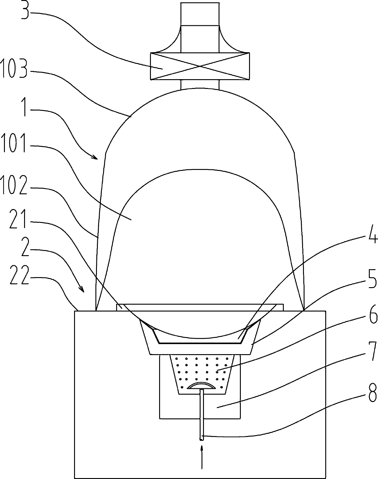
[0042] Such as Figure 1~7 Among them, a stove topping pot flame guide device, including a stove body 2, a furnace is provided in the stove body 2, a flame guide device 4 is provided between the upper part of the furnace hearth and the pot 9, and the space between the furnace hearth and the flame guide device 4 In communication with the chimney, a recessed portion 42 is provided on the flame guiding device 4 , and a cavity structure is formed between the recessed portion 42 and the bottom of the pot 9 . Preferably, a fire hole 43 or a fire grill 45 is provided in the recessed portion 42 . With this structure, the cavity structure between the recessed portion 42 and the bottom of the pot 9 maintains a positive pressure all the time, and the flame can be prevented from erupting toward the operator, thereby overcoming the influence of the pot upset on the operator. It should be noted that in the prior art, there is also a scheme of controlling the gas output to make the flame sm...

Embodiment 2

[0052] In a preferred solution, a smoke hood 1 that limits the section of the air inlet is provided above the cooker body 2, a smoke hood side wall 102 and the back side are provided with a smoke hood side wall 102, a smoke hood dome 103 is provided on the top, and a smoke hood dome 103 is provided on the front. An air inlet 101 is provided, and the cross section of the air inlet 101 is set such that when the exhaust fan 3 is activated, the inner cavity of the fume hood 1 is under negative pressure compared with the atmospheric environment. That is, when the exhaust fan 3 is started, the oxygen supply air enters the fume hood 1 from the air inlet 101 in the atmospheric environment under the negative pressure condition. With this structure, the efficiency of oil fume collection is greatly improved.

[0053] In a preferred solution, the distance between the side wall 102 of the fume hood and the stove body 2 is 0-30 cm. Specifically, the distance between the bottom of the arc-s...

Embodiment 3

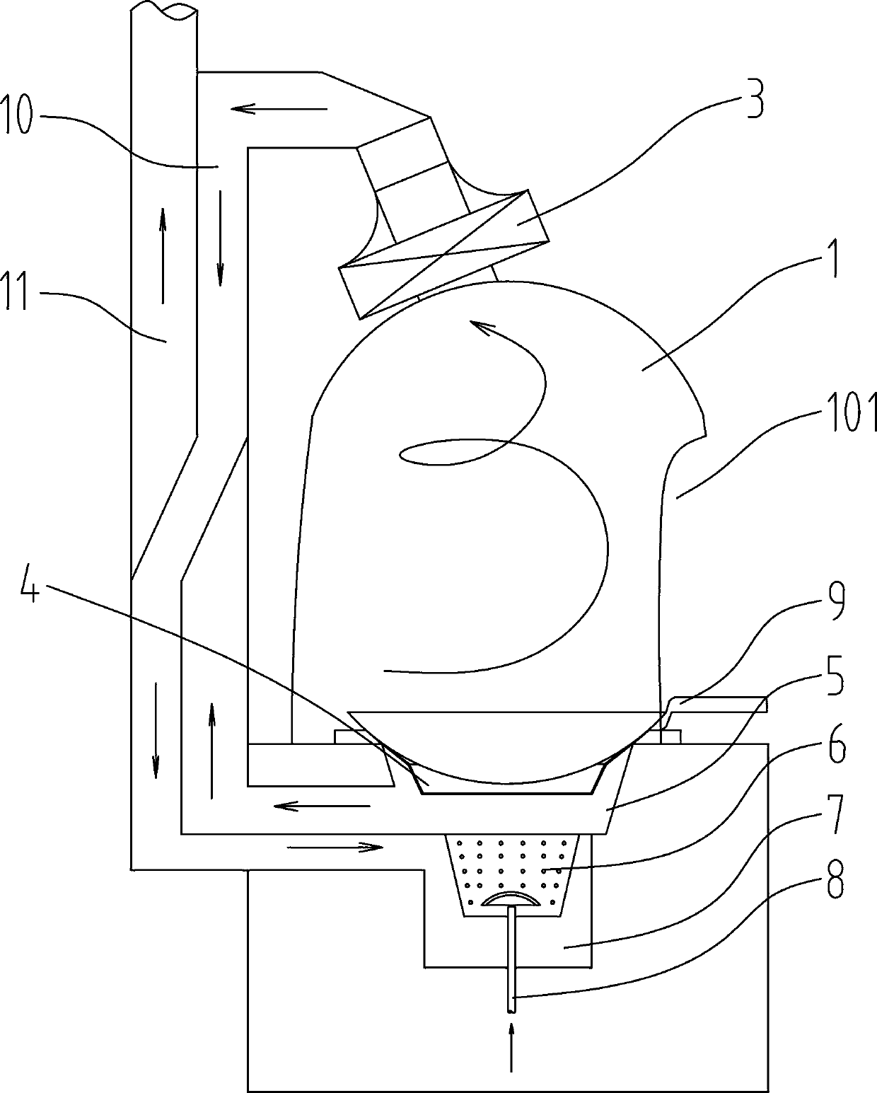
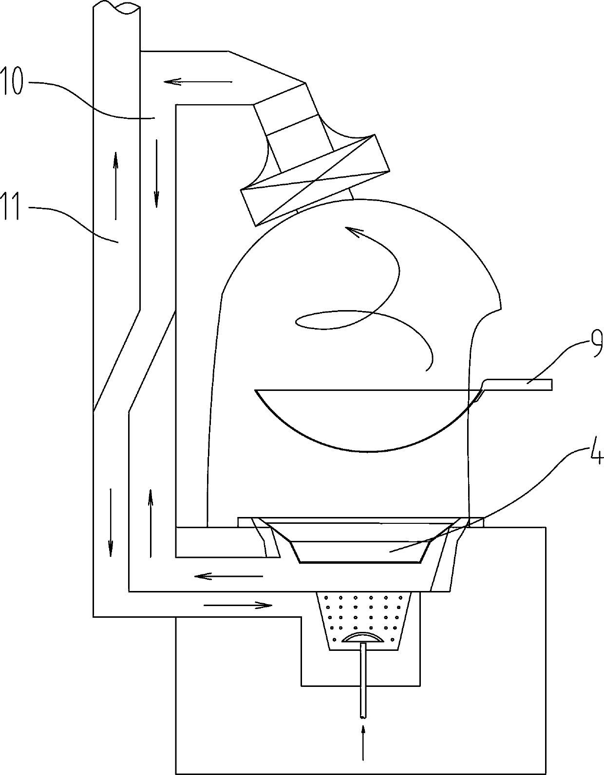
[0060] In a preferred scheme, the position near the top of the fume hood dome 103 is connected to the air inlet of the exhaust fan 3, and the air outlet of the exhaust fan 3 is connected to the oil fume passage 10, and the oil fume passage 10 is connected to the air inlet chamber 7 in the furnace, and the air inlet chamber 7 communicates with the mixing chamber 6 through the porous net, the gas pipe 8 communicates with the mixing chamber 6, the upper part of the mixing chamber 6 is provided with a combustion chamber 5, the combustion chamber 5 is connected with the fire channel 11, the fire channel 11 is connected with the chimney, and the combustion chamber 5 is located Below the flame guide device 4; with this structure, the collected oil fume passes through the oil fume passage 10 from the air inlet chamber 7, passes through the porous mesh, and enters the combustion chamber 5 after the mixing chamber 6 is fully mixed with the gas from the gas pipe 8 Combustion, the high-tem...


PUM


Abstract

The invention provides a cooking range tossing flame guide structure and a flame guide device. The cooking range tossing flame guide structure comprises a range body, and a hearth is arranged in the range body. The flame guide device is arranged between the upper part of the hearth and a pan, and the space between the hearth and the flame guide device communicates with a chimney. A sunk part is formed in the flame guide device, and a cavity structure is formed between the sunk part and the bottom of the pot. In the preferred scheme, a fire through hole is formed in the sunk part or a fire through gate are arranged at the sunk part. By the flame guide device arranged between the upper part of the hearth and the pan, the cooking range tossing flame guide structure solves the problem of the damage of pressure adaptation of an oil smoke circulation channel caused by tossing. After the flame guide structure and the flame guide device are arranged, the exhaust jet flow of flame is very small, so that the oil smoke collection cannot be influenced; or as the exhaust jet flow of flame is less, the exhaust and the oil smoke can be collected by an exhaust fan together. After being used for awhile, the flame guide device (4) can store more heat, and therefore the effect of dish heating is improved.

Description

technical field [0001] The invention relates to the field of household or commercial stoves, in particular to a stove top flame guide structure and a flame guide device that do not spray out a large amount of flames and affect oil fume collection when the cooker is turned over. Background technique [0002] Recently, the public is very disgusted with the oily fumes produced by catering stoves. In homes or communities, the exhaust of oily fumes produced by household or commercial stoves is a hot spot for complaints. And the smoke exhaust ventilator that adopts indoor is usually difficult to meet the user's requirement. [0003] Existing range hoods commonly used have following several structures, 1, up-pumping type, such as the cooker range hood recorded in Chinese patent document CN1246641C, adopts an upper cover body, blower fan is set on the upper cover body, and oil fumes are collected by the cover body , and discharged from the fan. But although various improvements ha...

Claims


Application Information

Patent Timeline
IPC IPC(8): F24C15/20F23G7/06
CPCF23G7/065F24C15/2071
Inventor 张跃虎
Owner 张跃虎
Why Eureka
Try Eureka