
Part feeding and discharging equipment and part feeding and discharging method

A technology of parts, material feeding and discharging, which is applied in the field of parts feeding and discharging equipment, which can solve the problems of reduced performance, high requirements for programming/testing time, high requirements for programming/tester status, and inability to take and discharge materials at the same time. , to achieve the effect of improving efficiency, improving the efficiency of feeding and discharging materials, and saving the time of picking and placing

Pending Publication Date: 2018-08-10
苏州河汉电子有限公司
View PDF0 Cites 0 Cited by
  • Summary
  • Abstract
  • Description
  • Claims
  • Application Information

AI Technical Summary

Problems solved by technology

The feeding and unloading actions cannot be carried out at the same time, which greatly reduces the efficiency
For example, IC chip programming / testing system, the current maximum efficiency of this method of feeding and discharging materials is only 3000UPH, and it has high requirements on the programming / testing time, chip type and the state of the programming / tester

Method used


Image

  • Part feeding and discharging equipment and part feeding and discharging method
  • Part feeding and discharging equipment and part feeding and discharging method
  • Part feeding and discharging equipment and part feeding and discharging method

Examples


Embodiment Construction

[0036] The present invention will now be described in further detail with reference to the accompanying drawings. These drawings are all simplified schematic diagrams, and only illustrate the basic structure of the present invention in a schematic manner, so they only show the structures related to the present invention.

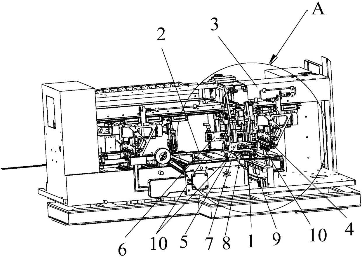
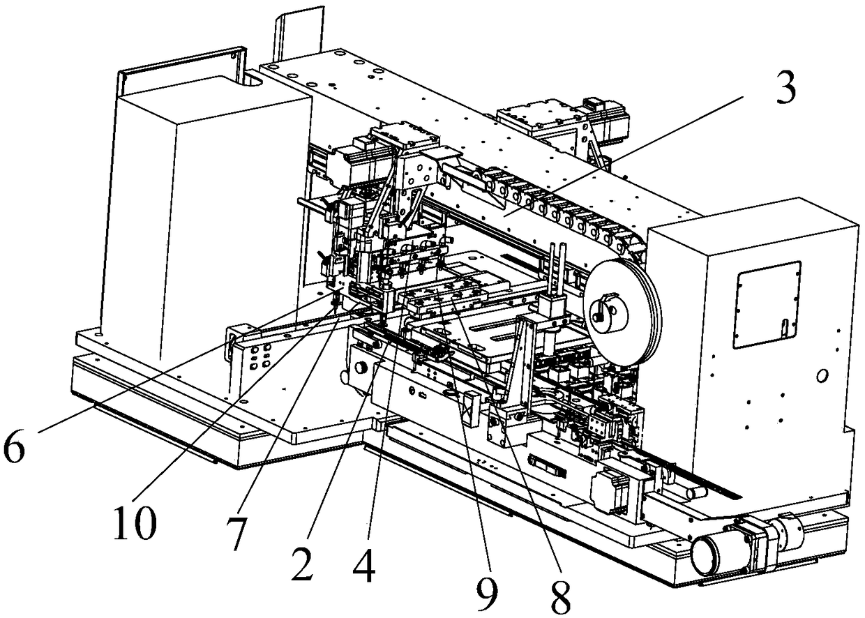
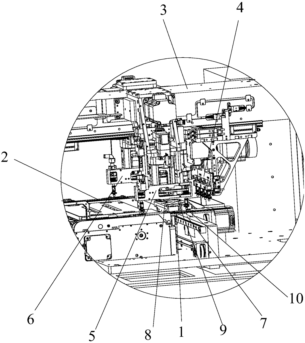
[0037] like Figure 1-Figure 3 A part feeding and discharging equipment of the present invention shown includes a feeding device 1 for feeding the parts 11 to be processed, a discharging device 2 for conveying the processed parts 11 out, and a beam. 3. The main arm 4 sliding along the beam 3, the feeding rotating arm 5 and the discharging rotating arm 6 respectively fixed on both sides of the beam 3, the longitudinal rail 7 arranged below the beam 3 and perpendicular to it, respectively along the longitudinal rail 7 The sliding feeding shuttle 8 and the discharging shuttle 9; the lower ends of the feeding rotating arm 5 and the discharging rotating arm 6 ea...


PUM


Abstract

The invention belongs to the technical field of automatic production of parts, and relates to part feeding and discharging equipment and a part feeding and discharging method. The part feeding and discharging equipment comprises a feeding device, a discharging device, a main arm, a feeding rotating arm, a discharging rotating arm, a feeding sliding shuttle and a discharging sliding shuttle; the feeding rotating arm and the discharging rotating arm are each provided with two suction nozzles; for each of the feeding rotating arm and the discharging rotating arm, one suction nozzle sucks parts, and meanwhile, the other suction nozzle puts down the parts sucked by the above suction nozzle; and the feeding rotating arm sucks the unprocessed parts on the feeding device and then places the unprocessed parts into the feeding sliding shuttle after rotating by 180 degrees, the main arm sucks and places the parts in the feeding sliding shuttle into a part processing area at the same time and places the processed parts into the discharging sliding shuttle, and one suction nozzle of the discharging rotating arm sucks the processed parts and then places the processed parts into the discharging device after rotating by 180 degrees. According to the equipment and the method, through the cooperative operation of the three arms, the traditional feeding and discharging maximum efficiency is improved from 3000 UPH to 4000 UPH.

Description

technical field [0001] The invention belongs to the technical field of automatic production of parts, and in particular relates to a device and method for feeding and discharging parts. Background technique [0002] IC chip programming / testing system or camera module testing system, etc., the incoming and outgoing of parts and components often pass through a mechanical arm, which performs both the reclaiming action and the discharging action. The reclaiming and discharging actions cannot be performed at the same time, which greatly reduces the efficiency. For example, the IC chip programming / testing system, the current maximum efficiency of this method of loading and unloading is only 3000UPH, and it has higher requirements on the programming / testing time, chip type and the status of the programming / tester. SUMMARY OF THE INVENTION [0003] The purpose of the present invention is to overcome the defect of low material feeding and discharging efficiency existing in the pri...

Claims


Application Information

Patent Timeline
Patent Type & Authority Applications(China)
IPC IPC(8): B65G47/91
CPCB65G47/915B65G47/918
Inventor 洪丽月刘勇志
Owner 苏州河汉电子有限公司
Learn More