Middle rail box girder for large-tonnage bridge crane and manufacturing method of middle rail box girder
A technology of bridge cranes and box girders, which is applied in manufacturing tools, track systems, transportation and packaging, etc., and can solve the problems of the middle rail box girders being limited by the lifting capacity
- Summary
- Abstract
- Description
- Claims
- Application Information
AI Technical Summary
Problems solved by technology
Method used
Image
Examples
Embodiment 1
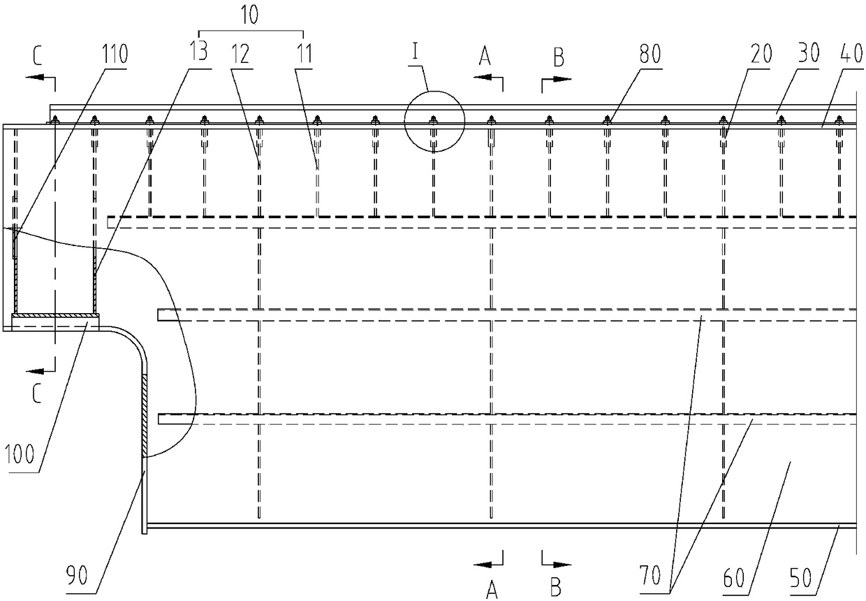
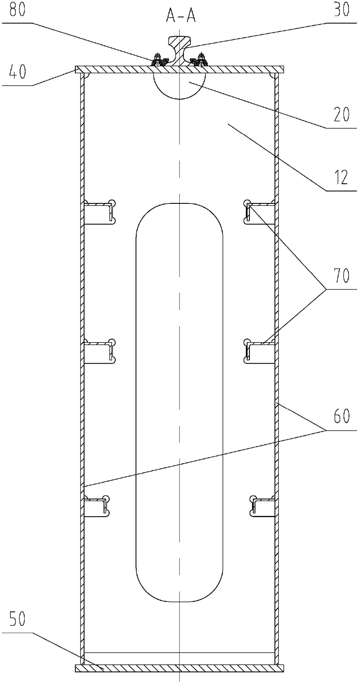
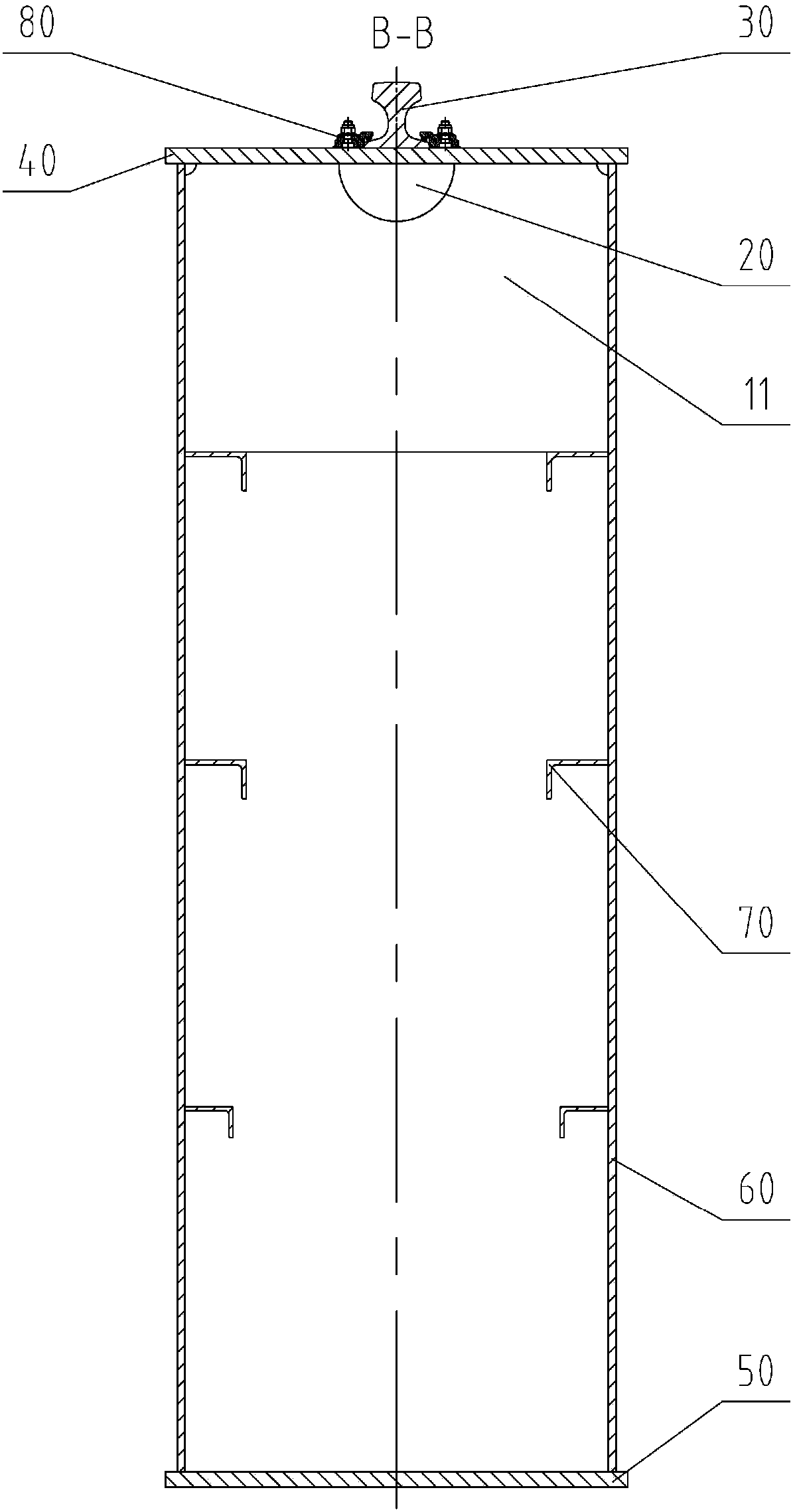
[0047] Refer to attached figure 1 And attached figure 2 As shown, a middle-rail box girder for a large-tonnage bridge crane includes transverse ribs 10, reinforcing plates 20, rails 30, upper flanges 40, lower flanges 50, webs 60, longitudinal ribs 70, Track pressing plate 80, large bent plate 90, half shaft sleeve 100, plug plate 110. The transverse ribs 10 include small transverse ribs 11, large transverse ribs 12 and end transverse ribs 13. The upper flange plate 40, the lower flange plate 50, and two webs 60 form a box beam. The longitudinal ribs 70 and the transverse rib 10 are arranged inside the box girder, and the large bent plate 90 is arranged at the end of the box girder. The middle part of the upper end of the transverse rib 10 is in close contact with the upper flange plate 40, and the rest is fixedly connected with the upper flange plate 40 , both sides of the transverse rib 10 are respectively fixedly connected with the web 60 , the upper end of the web 60 is...
example 2
[0057] The difference between example 2 and example 1 is that example 2 has increased the edge plate of the through hole of the large transverse rib plate, and the rest are the same, refer to the attached Figure 8 , attached Figure 9 And attached Figure 10 As shown, the through hole trimming board includes a vertical trimming board 126 and a horizontal trimming board 127, the vertical trimming board 126 is arranged on the left and right sides of the through hole 123, and the horizontal trimming board 127 is arranged on the upper and lower sides of the through hole 123 Both sides are perpendicular to the plate body 121 and are fixedly connected with it, and the two ends of the horizontal trim board 127 are respectively fixedly connected with two vertical trim boards 126 .
[0058] The permissible extrusion stress between the transverse rib 10 and the upper flange 40 is 1.4 times that of welding without welding. Because the upper edge of the transverse rib 10 is tightly wel...
PUM
 Abstract
Description
Claims
Application Information
 - R&D
- Intellectual Property
- Life Sciences
- Materials
- Tech Scout
- Unparalleled Data Quality
- Higher Quality Content
- 60% Fewer Hallucinations
Browse by: Latest US Patents, China's latest patents, Technical Efficacy Thesaurus, Application Domain, Technology Topic, Popular Technical Reports.
© 2025 PatSnap. All rights reserved.Legal|Privacy policy|Modern Slavery Act Transparency Statement|Sitemap|About US| Contact US: help@patsnap.com


