A cathode device for batch electroplating metal heat sink elements

A technology for electroplating metals and components, applied in the direction of electrodes, etc., can solve the problems of no use value, inability to provide high uniformity, and thin metal heat sink components, so as to stabilize the current of the electroplating process, improve the electroplating effect, and improve the The effect of ohmic contact quality

Active Publication Date: 2019-06-21
NORTH ELECTRON RES INST ANHUI CO LTD
View PDF4 Cites 0 Cited by
  • Summary
  • Abstract
  • Description
  • Claims
  • Application Information

AI Technical Summary

Problems solved by technology

The reasons are as follows: 1. Metal heat sink components are slender in appearance and size, and the existing electroplating cathode devices cannot be clamped; 2. Different from the planar technology of wafer surface electroplating, metal heat sink components are mostly body-type electroplating, that is, the surface of the body needs to be electroplated. Uniform electroplating, the existing electroplating cathode device cannot provide high uniformity and has no use value

Method used


Image

  • A cathode device for batch electroplating metal heat sink elements
  • A cathode device for batch electroplating metal heat sink elements
  • A cathode device for batch electroplating metal heat sink elements

Examples


Embodiment Construction

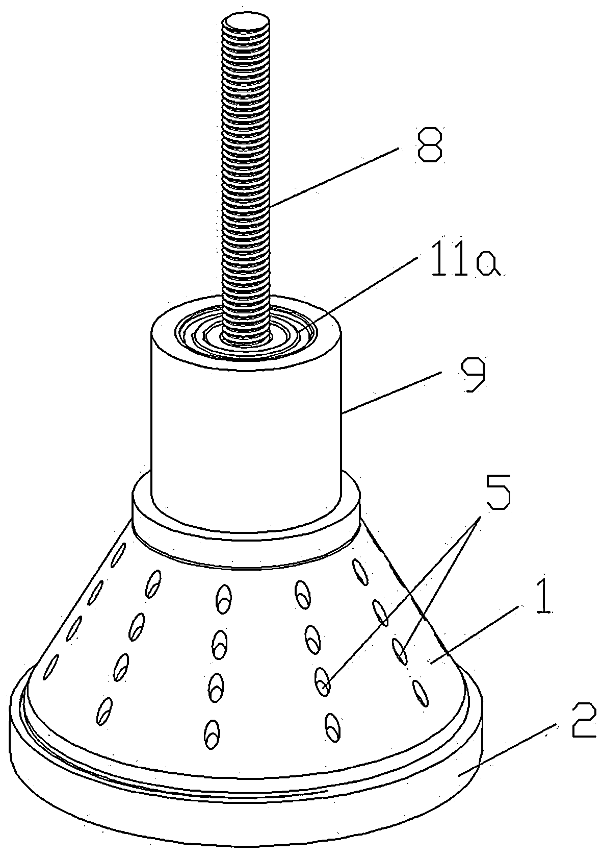
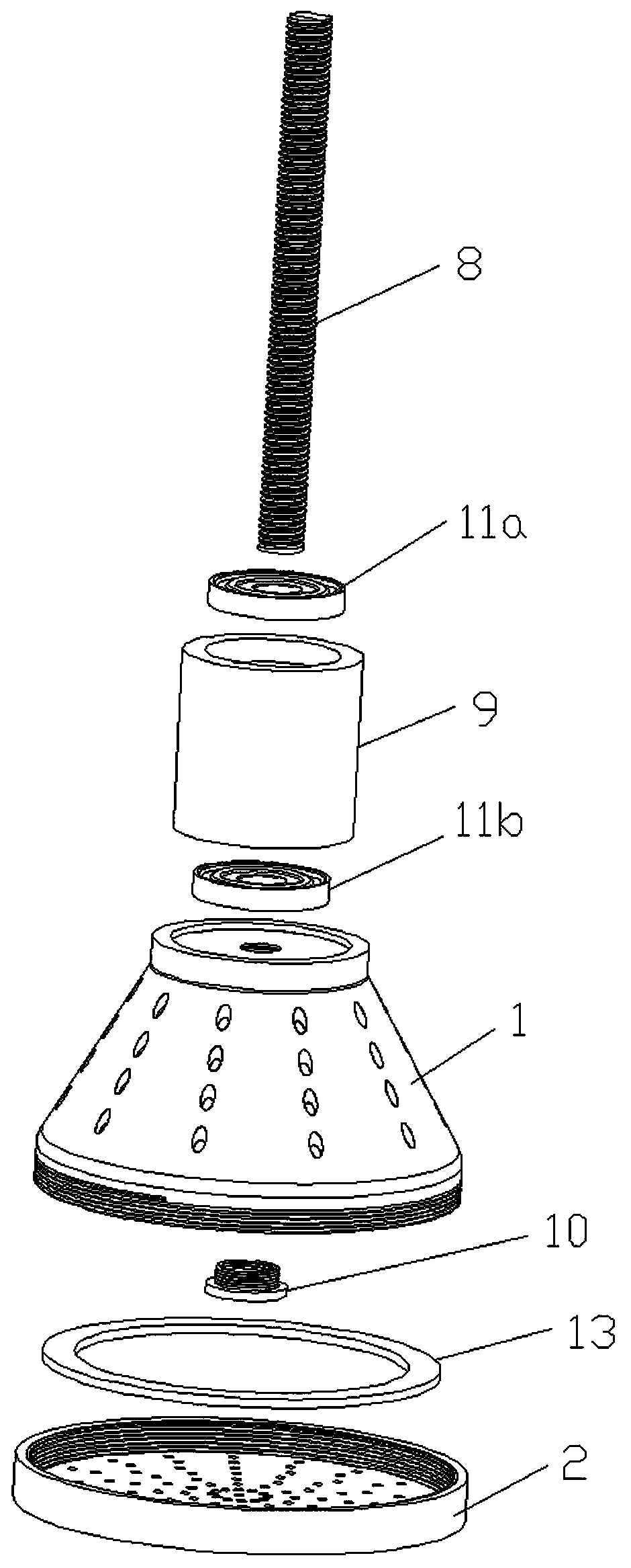
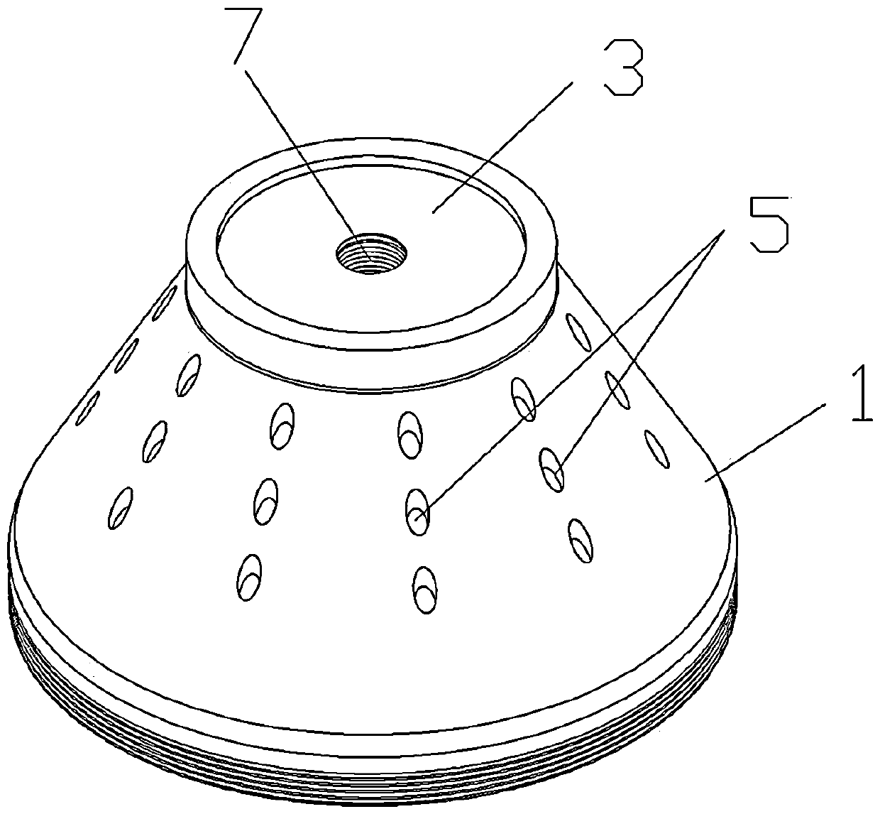
[0031] combine figure 1 and figure 2 As shown, the present invention provides a cathode device for batch electroplating metal heat sink elements, including a loading case 1 and a loading tray 2; Figure 3-5 As shown, the loading case 1 is in the shape of a truncated cone, the top surface of the loading case 1 is provided with a conductive sheet 3, and the inner side of the bottom of the loading case 1 is provided with a conductive ring 4; The hole array 5, the shell wall of the loading case 1 is also embedded with a group of metal leads 6, the top of the metal leads 6 is connected with the conductive sheet 3, and the bottom end is connected with the conductive ring 4; as preferred, the metal leads 6 Contains four, evenly distributed in the shell wall of the loading shell 1.

[0032] The center of the conductive sheet 3 is provided with a screw hole 3a, and the top of the loading case 1 is provided with a mounting hole 7 concentric with the screw hole 3a. The mounting hole 7...


PUM


Abstract

The invention discloses a cathode device for batch plating of metal heat sink components. The cathode device comprises a loading cover and a loading tray. The loading cover is in a circular truncatedcone shape. A conducting plate is arranged on the top face of the loading cover. A conducting ring is arranged on the bottom edge of the loading cover. The cover wall of the loading cover is providedwith an electroplating solution through hole array. A set wire leads are inlaid in the cover wall of the loading cover. The top ends of the metal leads are connected with the conducting plate, and thebottom end of the metal leads are connected with the conducting ring. The loading tray is connected with the bottom of the loading cover in a screw-thread fit mode to form a loading cavity used for containing the metal heat sink components. The loading tray is provided with a set of electroplating solution flow holes. A screw hole is formed in the center of the conducting plate. The top of the loading cover is provided with a mounting hole concentric with the screw hole. A conducting post is arranged in the mounting hole in a penetration mode and used for being in threaded connection with a cathode connector of electroplating equipment. Through the cathode device, there is no need to clamp the metal heat sink components, and an electroplating solution flows into and out of the loading cavity to achieve electroplating. The cathode device is simple in structure, convenient to install, good in stability, high in electroplating uniformity and capable of meeting the requirements for electroplating of the metal heat sink components.

Description

technical field [0001] The invention relates to the technical field of preparation of integrated circuit components, in particular to a cathode device for batch electroplating metal heat sink components. Background technique [0002] In the field of integrated circuit manufacturing, electroplating technology is often used in the preparation of metal thin films due to its simple working conditions and various types of metals. At present, electroplating equipment is mostly used for wafer-level surface processing technologies such as wafer-level linear growth, wafer-level selective growth, and TSV preparation. The electroplating cathode device used in the electroplating equipment also adopts a multi-point clamping method to realize wafer clamping. [0003] It is worth noting that power devices in the field of integrated circuits release a lot of heat when they are working, and they need to be channeled from the working environment to the external environment in time. The most ...

Claims


Application Information

Patent Timeline
Patent Type & Authority Patents(China)
IPC IPC(8): C25D17/12
CPCC25D17/12
Inventor 房立峰陈丙根陈计学刘阳张帅王帆
Owner NORTH ELECTRON RES INST ANHUI CO LTD
Why Eureka
Try Eureka