Infrared image and visible image fusion method

An infrared image and image fusion technology, which is applied in the field of infrared and visible light image fusion, can solve the problems of long computing time, unclear fusion images, and high computing complexity

Inactive Publication Date: 2018-08-10
HEBEI UNIVERSITY
View PDF9 Cites 32 Cited by
  • Summary
  • Abstract
  • Description
  • Claims
  • Application Information

AI Technical Summary

Problems solved by technology

[0005] The purpose of the present invention is to provide an image fusion method of infrared and visible light to solve the problems of unclear, incomplete details, high computational complexity and long computational time in existing fusion images

Method used


Image

  • Infrared image and visible image fusion method
  • Infrared image and visible image fusion method
  • Infrared image and visible image fusion method

Examples


Embodiment 1

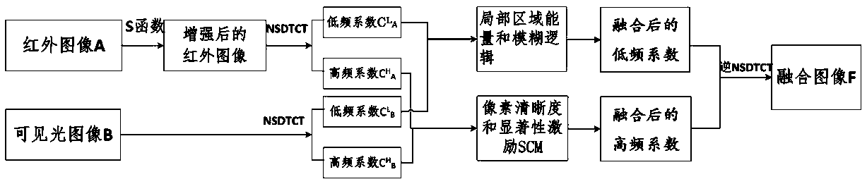
[0040] In this embodiment, the infrared image is marked as image A, and the visible light image is marked as image B.

[0041] Step 1: Use the S function to enhance the contrast of the original infrared image A.

[0042] The original infrared image A as Figure 4 As shown in (a), it is the infrared image of "UN Camp" in the gallery.

[0043] In the present invention, S function is defined as:

[0044]

[0045]In formula (1), A(i, j) is the pixel gray value of the original infrared image at position (i, j); S(i, j) is the pixel gray value at position (i, j) after the contrast enhancement of the original infrared image The gray value of the pixel at ; k is the inflection point parameter; "*" means the multiplication sign;

[0046] The expression of k is as follows:

[0047]

[0048] In formula (2), μ is the mean value of the pixel gray value of the original infrared image.

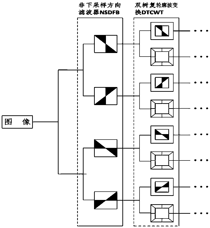
[0049] Step 2: Decompose the enhanced infrared image and the original visible light image usin...


PUM


Abstract

The invention provides an infrared image and visible image fusion method. The method comprises the following steps of: firstly decomposing an infrared image and a visible image by adoption of non-subsampled double-tree contourlet transformation NSDTCT so as to obtain a low-frequency sub-band and a high-frequency sub-band; constructing a fused sub-band coefficient; in low frequency, calculating local area energy, and replacing a low-frequency sub-band coefficient in fuzzy logic (constructed by a fuzzy membership and a Gaussian function) by the local area energy to calculate a weight coefficient, so as to calculate a fused low-frequency sub-band coefficient; in high frequency, taking pixel definition and significance as fusion rules externally input by a pulse granted cortex model SCM so asto calculate a fused high-frequency sub-band coefficient; and finally obtaining a fused image via inverse NSDTCT. Compared with the traditional image fusion method, the method subjectively and objectively obtains relatively ideal effects in infrared image and visible image fusion, and provides a new thought for infrared image and visible image fusion.

Description

technical field [0001] The invention relates to the technical field of image fusion, in particular to an image fusion method of infrared and visible light. Background technique [0002] Infrared and visible light image fusion has been widely used in military and civilian fields due to its own characteristics. Infrared technology can effectively capture hidden heat source targets in a complex environment according to different thermal radiation information emitted by different objects, and can well cope with the influence of factors such as light, climate, and shelter, and has the ability to identify camouflage. However, because the infrared image is not sensitive enough to the brightness change of the scene, it results in low contrast and poor resolution, making the background very blurred. Visible light images can provide more texture details in line with human visual perception, and can better reflect the overall picture of the scene where the target is located. However, ...

Claims


Application Information

Patent Timeline
Patent Type & Authority Applications(China)
IPC IPC(8): G06T3/40G06T5/50
CPCG06T3/4061G06T5/50G06T2207/10004G06T2207/10048G06T2207/20024G06T2207/20048G06T2207/20084
Inventor 赵杰李易瑾刘静马玉娇丁雪桐
Owner HEBEI UNIVERSITY
Why Eureka
Try Eureka