Control cable separation bracket for electric power secondary system

A power secondary system and control cable technology, applied in the direction of overhead lines/cable equipment, circuits, electrical components, etc., can solve the problems of not being able to supply power in time, difficult and inconvenient management and maintenance, and achieve the effect of convenient management and maintenance

Pending Publication Date: 2018-08-10
HUAIBEI POWER SUPPLY COMPANY OF STATE GRID ANHUI ELECTRIC POWER +1
View PDF0 Cites 2 Cited by
  • Summary
  • Abstract
  • Description
  • Claims
  • Application Information

AI Technical Summary

Problems solved by technology

Nowadays, the control cable brackets of the power secondary system are mostly inseparable brackets. Although the effect of fixing cables is better, ordinary brackets cannot be broken in time for the damaged parts of the control cables of the power secondary system because they are not separable. Power supply cannot be supplied in time after maintenance, so it brings difficulties and inconvenience to both management and maintenance. For this reason, the present invention proposes a control cable separation bracket for the secondary power system

Method used


Image

  • Control cable separation bracket for electric power secondary system
  • Control cable separation bracket for electric power secondary system
  • Control cable separation bracket for electric power secondary system

Examples


Embodiment Construction

[0021] The following will clearly and completely describe the technical solutions in the embodiments of the present invention with reference to the accompanying drawings in the embodiments of the present invention. Obviously, the described embodiments are only some, not all, embodiments of the present invention. Based on the embodiments of the present invention, all other embodiments obtained by persons of ordinary skill in the art without making creative efforts belong to the protection scope of the present invention.

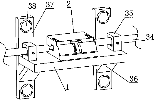
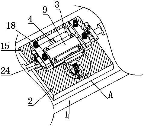
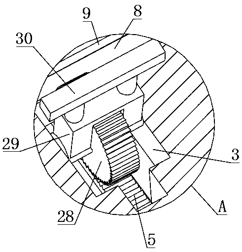
[0022] see Figure 1-10 , the present invention provides a technical solution: a control cable separation bracket for a power secondary system, including a support plate 1, a main box 2 is provided on the upper side of the support plate 1, and a second A cavity 3, the bottom of the first cavity 3 is provided with a chute 4, the inside of the chute 4 is slidably connected with a rack 5, the upper side of the rack 5 is meshed with a gear 28, the The gear 28 is ...


PUM


Abstract

The invention discloses a control cable separation bracket for an electric power secondary system. The control cable separation bracket comprises a supporting plate, the upper side of the supporting plate is provided with a main box, a first cavity is formed in the main box, a sliding slot is formed in the bottom of the first cavity, a rack is slidingly connected in the sliding slot, the upper side of the rack is meshed with a gear, the gear is rotatably connected to the side wall of the first cavity and fixedly connected to a rotating block, and the upper side of the rotating block is fixedlyconnected to a rotating handle. One end of an arc-shaped copper piece is fixedly connected with a copper block, the copper block is disposed in a third cavity, the third cavity is formed in the side,away from the first cavity, of a second cavity, and fixing blocks are fixedly connected to the two ends of the upper side of the supporting plate respectively. A cable penetrates through a cable passing slot, and then a second bolt pushes a cable clamping block so that the cable at both ends of a bracket body can be fixed on the bracket body. By pushing the rotating handle, the gear rotates to drive the two ends of a copper column to move between an upper clamping block and a lower clamping block. The two ends of the copper column and the corresponding arc-shaped copper piece are separated and combined, so that the circuit of the cable at both ends is disconnected or connected, and separated control over the electric power secondary system is achieved.

Description

technical field [0001] The invention relates to the technical field of power facilities, in particular to a separation bracket for control cables of a power secondary system. Background technique [0002] As we all know, electric power enterprises are not only the basic guarantee for the development and construction of my country's national economy, but also an important means to improve the living standards of our people. The installation quality of the control cables of the power secondary system is the basis for the safety, reliability and coordinated development of the power system. Nowadays, the control cable brackets of the power secondary system are mostly inseparable brackets. Although the effect of fixing cables is better, ordinary brackets cannot be broken in time for the damaged parts of the control cables of the power secondary system because they are not separable. Electricity and maintenance can not be powered in time, so it is difficult and inconvenient for ma...

Claims


Application Information

Patent Timeline
Patent Type & Authority Applications(China)
IPC IPC(8): H01R11/03H01R11/09H02G1/04
CPCH01R11/03H01R11/09H02G1/04
Inventor 孙振兴吕洪明朱思杰赵峻岭
Owner HUAIBEI POWER SUPPLY COMPANY OF STATE GRID ANHUI ELECTRIC POWER
Why Eureka
Try Eureka