
Anti-electric shock electrical connector and module socket employing same

A technology of electrical connectors and electrical connecting pieces, which is applied to the parts, connections, and two-component connecting devices of the connecting device, which can solve the problems of only benefiting the production end and cumbersome operation process, so as to avoid electric shock accidents and improve safety , the effect of preventing accidental electric shock

Pending Publication Date: 2018-08-10
马鞍山虹迈专业化设计有限公司
View PDF0 Cites 4 Cited by
  • Summary
  • Abstract
  • Description
  • Claims
  • Application Information

AI Technical Summary

Problems solved by technology

Not only is the operation process cumbersome, but there are also electric shock accidents caused by improper operation.
Now the modular socket is popular, but most of the existing modular sockets adopt the installation method of sealing and isolation welding, which makes it only beneficial to the production end.

Method used


Image

  • Anti-electric shock electrical connector and module socket employing same
  • Anti-electric shock electrical connector and module socket employing same
  • Anti-electric shock electrical connector and module socket employing same

Examples


Embodiment 1

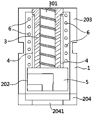
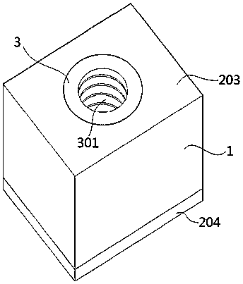
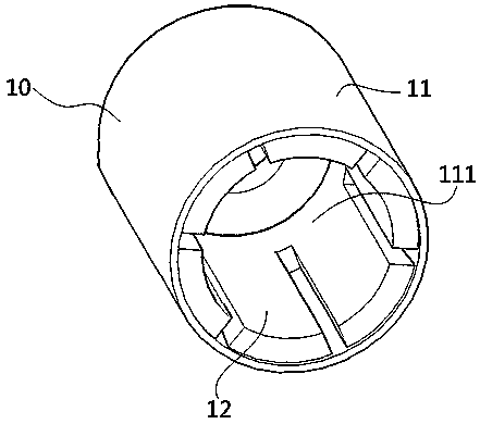
[0065] Such as Figure 1-4 As shown, an electric shock-proof connector in this embodiment includes an electrical connector male (1) and an electrical connector female (10). The electrical connector male (1) comprises a male housing (2), an insulator (3), a conductive sheet (4), a base (5) and a spring (6).

[0066] The male shell (2) includes a male upper shell (203) and a male lower shell (204). At least one of the male upper shell (203) and the male lower shell (204) has a cavity structure. The male upper shell (203) is fixedly connected to the male lower shell (204) by clamping or screws. The male upper shell (203) and the male lower shell (204) together form a limiting cavity (202). There is an action hole (201) on the top surface of the male head upper shell (203), and a wire inlet hole (2041) is arranged on the male head lower shell (204). Both the action hole (201) and the wire inlet hole (2041) communicate with the limiting cavity (202).

[0067] The outer diamete...

Embodiment 2

[0079] The main body structure of the electric shock-proof male connector of this embodiment is basically the same as that of the electrical connector male described in Embodiment 1, the difference is that: on the outer wall of the male housing (2), A locking structure (7) consisting of grooves or sheet-shaped side wings is provided, and holes may be provided on the side wings. The electrical connector male head (1) is installed on the external device by clamping the locking structure (7) on the external track, or fixedly connecting the external device with screws.

[0080] In this embodiment, on the outer wall of the male housing (2), there may be provided a clamping foot or a clamping slot for clamping with an external device.

Embodiment 3

[0082] An electric shock-proof male connector of this embodiment, the main structure is basically the same as that of the electrical connector male described in Embodiment 2, the difference is that it also includes a ferrule (8); the ferrule ( 8) It is a nut structure.

[0083] The outer wall part between the head of the male upper shell (203) or the tail of the male lower shell (204) and the locking structure (7) is a threaded column structure. The ferrule (8) can be screwed on the outer side wall of the male upper shell (203) or the male lower shell (204). The locking position of the ferrule (8) is on one side of the locking structure (7), close to the locking structure (7). When the male electrical connector (1) is clamped to the outer track, the male electrical connector (1) can be squeezed to one side of the track by twisting the ferrule (8), and finally locked.


PUM


Abstract

The present invention provides an anti-electric shock electrical connector. The anti-electric shock electrical connector comprises an electrical connector male connector and electrical connector female bases. The electrical connector male connector comprises a male connector housing, an insulation body, conducting strips, a pedestal and springs. The conducting strips are installed at the outer surface of the insulation body which is fixedly connected with the pedestal located in the male connector housing, and the top end of the insulation body is provided with a threaded hole. the male connector housing is provided with motion holes, and the insulation body can drive the conducting strips to penetrate the motion hole and to be exposed out of the male connector housing. The springs sleevethe insulation body located between the male connector housing and the pedestal to form resumeelasticity. The electrical connector female bases are cavity structures internally provided with lotus-shaped contact pieces, the top ends of the electrical connector female bases are provided with screw installation holes, the openings at the bottom ends of the electrical connector female bases can allowthe insulation body in the electrical connector male connector to pass through. Screw rods with screws penetrates the electrical connector female bases to enter the threaded hole on the male connector insulation body, and the screw is twisted to allow the conducting strips in the male connector into the electrical connector female base to be in contact with the contact piece in the female base soas to connect with a circuit. The screw is loosened, and the conducting strips are taken back into the male connector housing under the action of the springs.

Description

technical field [0001] The invention belongs to the field of electrical components, and more specifically relates to an electric shock-proof connector and a modular socket using the connector. technical background [0002] With the development of science and technology, especially the diversification of electrical equipment in recent years, various modular electrical equipment have emerged one by one, and the frequency of people's contact with circuits is also on the rise. The electrical connectors under the current technical conditions include various types of connector male and female heads, plugs and sockets, etc. In the field of professional technology, many components and equipment are mostly connected by bare contacts; during the operation, the power supply, circuit breaker or switch is often used to control the charged state of the active end, so that the components to be connected are connected to the bare contacts. in the circuit. Not only the operation process is...

Claims


Application Information

Patent Timeline
IPC IPC(8): H01R24/28H01R24/20H01R13/15H01R13/642
CPCH01R24/28H01R13/15H01R13/642H01R24/20
Inventor 李利
Owner 马鞍山虹迈专业化设计有限公司
Learn More