Tweezers for clamping substrate in clean room

A clean room and substrate technology, applied in hand-held tools, manufacturing tools, etc., can solve the problems of substrate surface pollution, edge chipping, improper operation, etc., and achieve the effect of avoiding substrate slipping

Inactive Publication Date: 2018-08-14
湖州正鸣塑胶科技有限公司
View PDF0 Cites 3 Cited by
  • Summary
  • Abstract
  • Description
  • Claims
  • Application Information

AI Technical Summary

Problems solved by technology

The method of clamping the upper and lower surfaces of the substrate, because the angle between the two clamping arms is small, the substrates of different sizes can be firmly clamped, but the direct contact between the tweezers and the upper surface of the substrate is easy to cause contamination or contamination of the substrate surface. scratch
The method of clamping the side of the substrate can prevent the surface of the substrate from being polluted or scratched by direct contact with the tweezers, but there are two problems: on the one hand, for substrates with large size differences, it is necessary to replace tweezers of different sizes, Otherwise, the angle between the two clamping arms is too large, and the contact area between the tweezers arm and the side of the substrate is small, causing the substrate to slip; When it is large, it will still cause a large local stress on the sharp edge of the substrate side and cause substrate chipping, and the debris generated by the substrate chipping will contaminate the upper surface of the substrate
Therefore, the existing tweezers for clamping substrates in the clean room have the problems of chipping and contaminating the surface of the substrate when the tweezers need to be replaced when clamping the side of the substrate with a large size change.

Method used


Image

  • Tweezers for clamping substrate in clean room
  • Tweezers for clamping substrate in clean room

Examples


Embodiment Construction

[0011] The present invention will be further described below in conjunction with the accompanying drawings and embodiments, but not as a basis for limiting the present invention.

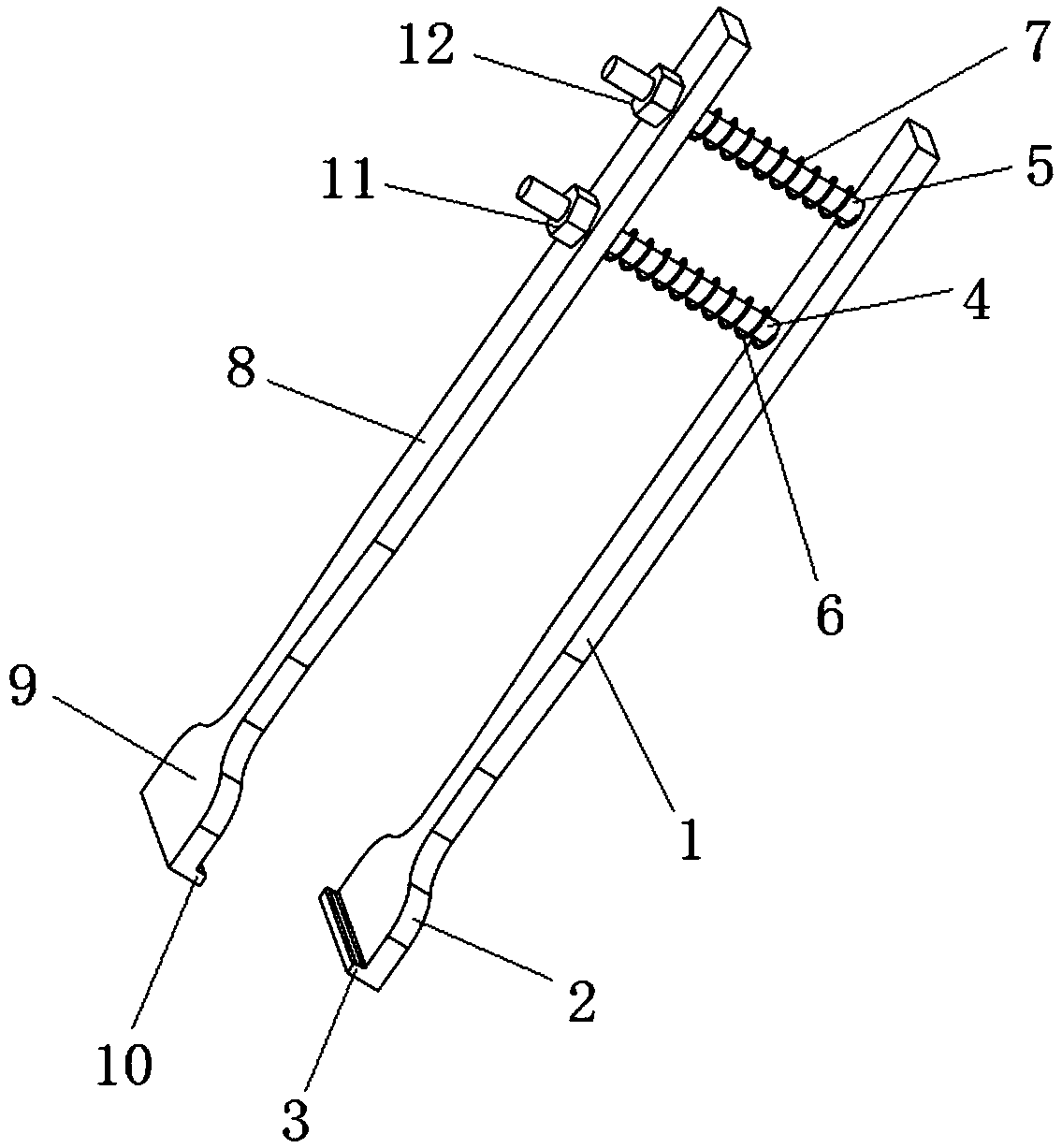
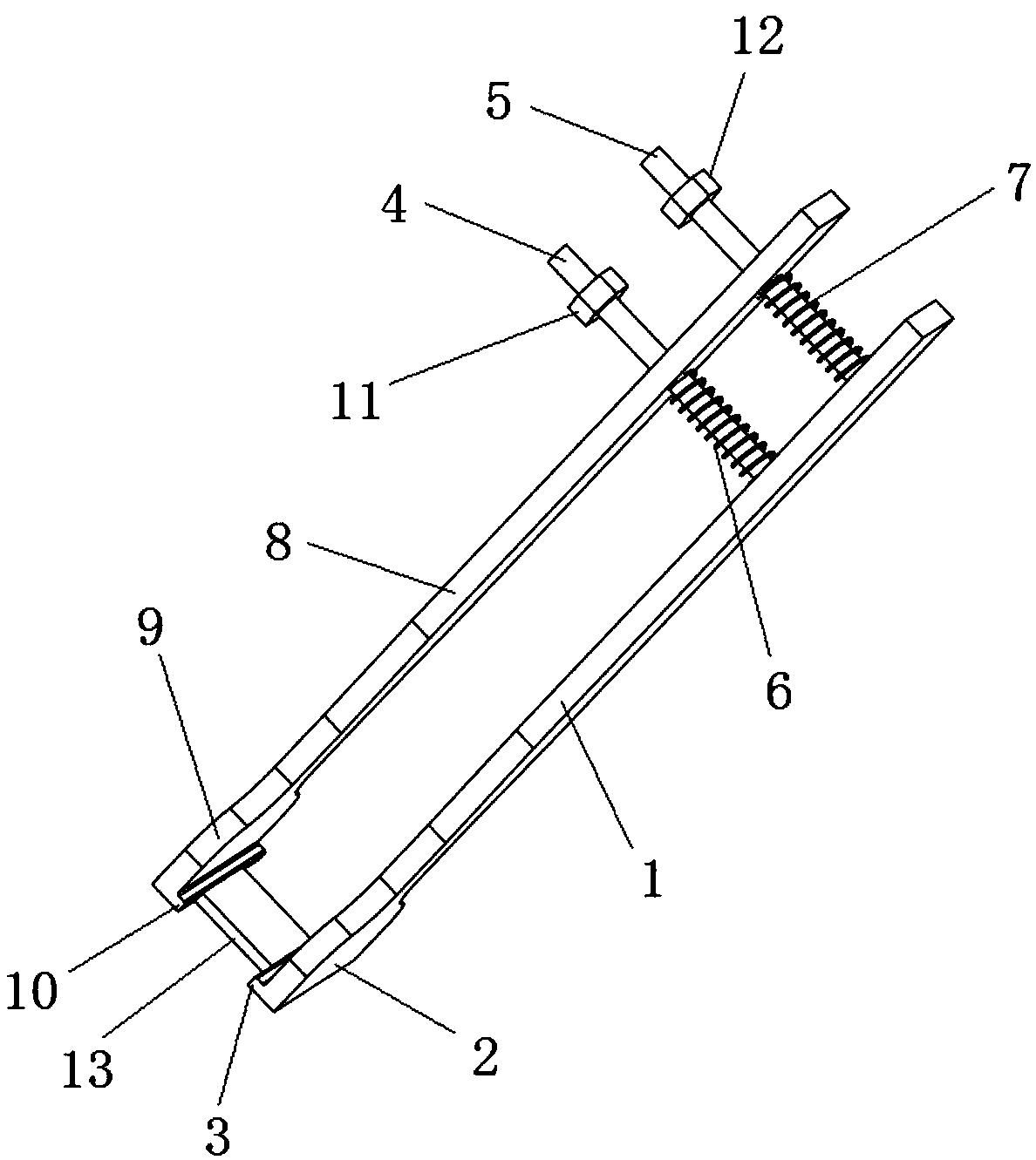
[0012] Example. A kind of tweezers used for clamping substrates in a clean room, constituted as Figure 1-2 As shown, the fixed arm 1 is included, the lower end of the fixed arm 1 is connected with the first splint 2, and the end edge of the first splint 2 is connected with the first rubber strip 3; A guide post 4 and a second guide post 5, the first guide post 4 and the second guide post 5 are connected with a movable arm 8, the lower end of the movable arm 8 is connected with a second splint 9, and the end edge of the second splint 9 is connected with a second glue Bar 10; the outer ring of the first guide post 4 is connected with the first spring 6, and the outer ring of the second guide post 5 is connected with the second spring 7; the end of the first guide post 4 near the movable arm 8 is con...


PUM


Abstract

The invention discloses tweezers for clamping a substrate in a clean room. The tweezers comprise a fixing arm. A first clamping plate is connected to the lower end of the fixing arm. A first rubber strip is connected to the edge of the tail end of the first clamping plate. The upper part of the fixing arm is connected with a first guide post and a second guide post of the fixing arm, wherein the first guide post and the second guide post are parallel to each other and perpendicular to the fixing arm, the first guide post and the second guide post are connected with a movable arm, a second clamping plate is connected to the lower end of the movable arm, and a second rubber strip is connected to the edge of the tail end of the second clamping plate. A first spring is connected to the outer ring of the first guide post, and a second spring is connected to the outer ring of the second guide post. A first fixing block is connected to the tail end, close to the movable arm, of the first guide post, and a second fixing block is connected to the tail end, close to the movable arm, of the second guide post. The tweezers have the beneficial effects that the tweezers do not need to be replaced when clamping the side edges of substrates with the large changes in size, and the edge collapse and pollution to the surfaces of the substrates do not occur.

Description

technical field [0001] The invention relates to a tweezers used for clamping substrates in a clean room. Background technique [0002] Tweezers are often used to hold the substrate when developing microelectronic devices, MEMS devices, etc. in a clean room. At present, the tweezers used for clamping the substrate in the clean room clamp the substrate by the rotational movement of the tweezers arm. The clamping methods include clamping the upper and lower surfaces of the substrate and clamping the side of the substrate. The method of clamping the upper and lower surfaces of the substrate, because the angle between the two clamping arms is small, the substrates of different sizes can be firmly clamped, but the direct contact between the tweezers and the upper surface of the substrate is easy to cause contamination or contamination of the substrate surface. scratched. The method of clamping the side of the substrate can prevent the surface of the substrate from being polluted...

Claims


Application Information

Patent Timeline
Patent Type & Authority Applications(China)
IPC IPC(8): B25B9/04
CPCB25B9/04
Inventor 林峰
Owner 湖州正鸣塑胶科技有限公司
Why Eureka
Try Eureka