

A method for improving the accuracy of the frame antenna profile
A frame and antenna technology, applied in the field of frame antenna profile design optimization, can solve the problems of reduced expansion ratio, increased overall antenna mass, and increased unit volume mass, so as to improve theoretical profile accuracy, ensure molding quality, and increase quantity. Effect
Active Publication Date: 2012-06-27
中国航天科技集团公司第五研究院第五0四研究所
View PDF0 Cites 5 Cited by
- Summary
- Abstract
- Description
- Claims
- Application Information
AI Technical Summary
Problems solved by technology
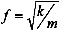
Shortening the length of the folding rod under the same antenna caliber will inevitably lead to more components such as rods, joints, faceplate nodes, springs, etc., and the structure is complicated, which will significantly increase the overall mass of the antenna, reduce the unfolding ratio, and increase the mass per unit volume. According to the formula, The increase of mass m will cause the fundamental frequency f of the antenna to decrease, and the increase of mass m and the decrease of fundamental frequency f will bring a series of mechanical problems
Method used
View moreImage
Smart ImageViewing Examples

Examples
Embodiment 1
Embodiment 2
Login to View More PUM
 Abstract
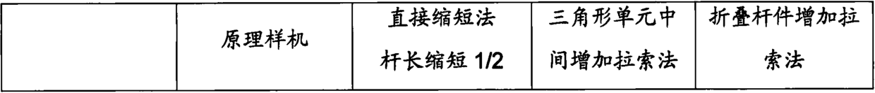
A method to improve the accuracy of the frame antenna profile. Firstly, the reflective mesh surface is separated from the folded rods and the faceplate nodes, and an adjustable support column of a certain height is added to the faceplate nodes, and then the reflective mesh surface is decomposed. Add adjustable cables on top, add straps between the adjustable support columns and adjustable cables, divide the triangular units on the upper surface of each frame into several small triangular units, and finally sew the reflective mesh on the straps . This method adopts the design idea of separating the frame structure from the reflective mesh surface, re-decomposes the reflective mesh surface, and increases the number of basic triangular units while keeping the quality characteristics, mechanical properties, and expansion methods of the main structure of the frame unchanged. The side length of the triangle unit is shortened, thereby improving the theoretical surface accuracy of the reflective mesh surface.
Description
technical field The invention relates to a method for optimizing the profile design of a frame antenna, in particular to a method for improving the profile precision of a frame antenna. Background technique With the development of satellite antenna technology, the application of large-aperture satellite antennas is becoming more and more extensive. Due to the limitations of satellite platforms and carrier windshields, this type of antenna usually adopts a deployable structure, that is, it needs to be folded in a certain state during the launch phase. Constraints, after the satellite enters the orbit, it will be deployed to reach the working state. As a frame-type expandable antenna suitable for making large and super large satellite antennas, it has the characteristics of small folded volume, large expansion and contraction ratio, light weight of the overall structure, and wide operating frequency band, and it is easy to realize multi-beam, multi-band and multi-polarization....
Claims
Login to View More Application Information
Patent Timeline
 IPC IPC(8): H01Q15/20H01Q1/08
Inventor方永刚郑士昆韦娟芳
Owner中国航天科技集团公司第五研究院第五0四研究所