A pulse current assisted micro-bending forming device and method for a thin metal plate
A technology of pulse current and metal sheet, which is applied in the direction of metal processing equipment, forming tools, manufacturing tools, etc., can solve the problems of difficult workpiece clamping, difficult to control forming, poor positioning accuracy, etc., to achieve the solution of difficult clamping, cost reduction, Solve the effect of poor mold positioning accuracy
- Summary
- Abstract
- Description
- Claims
- Application Information
AI Technical Summary
Problems solved by technology
Method used
Image
Examples
specific Embodiment approach 1
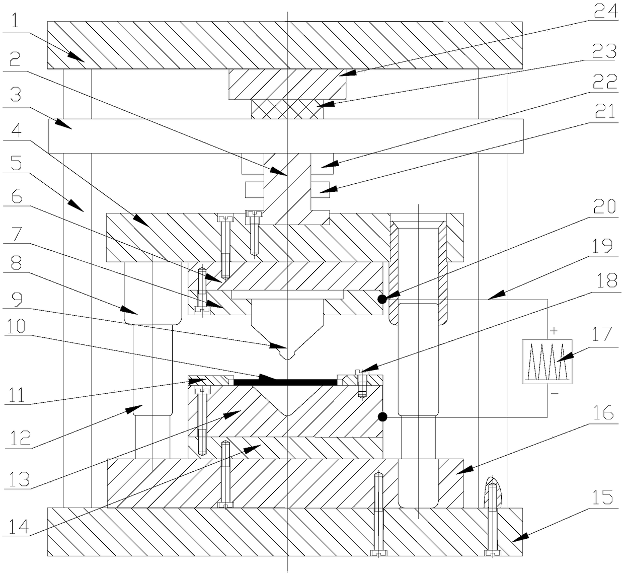
[0034] Specific implementation mode one: combine Figure 1 to Figure 4 Describe this embodiment. A pulse current assisted micro-bending forming device for a thin metal plate in this embodiment includes a mold assembly, a loading device, a pulse power supply system, and a control system. The mold assembly is installed in the loading device, and the pulse power supply system is connected to the mold assembly. The pulse is provided to the mold assembly, the loading device and the pulse power supply system are connected with the control system, and the mold assembly, the loading device and the pulse power supply system are automatically controlled through the control system.
[0035] Current-assisted forming refers to a processing technology that applies continuous current or pulse current to the blank while plastically deforming. Current research shows that applying current during the micro-forming process can reduce the influence of the scale effect, and the current for micro-be...
specific Embodiment approach 2
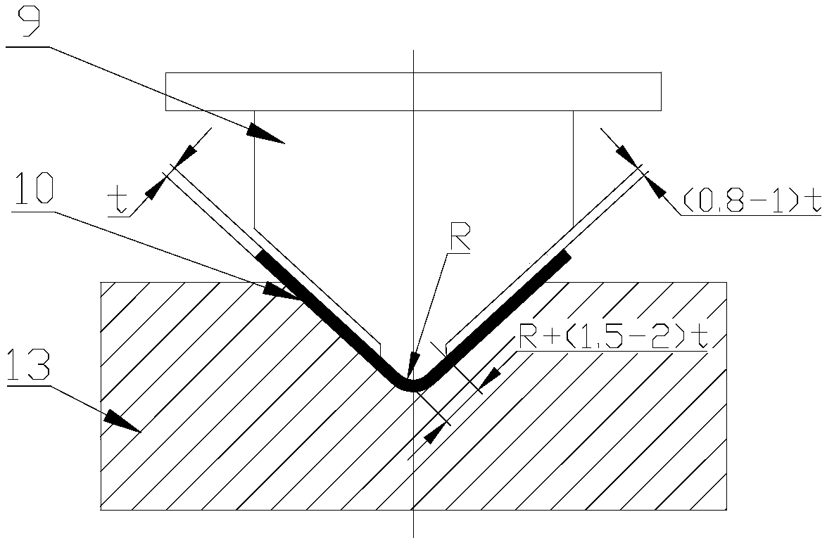
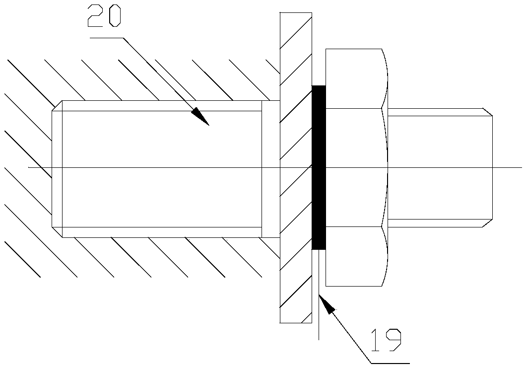
[0036] Specific implementation mode two: combination figure 1 Describe this embodiment, the mold assembly of this embodiment comprises upper template 4, upper insulating plate 6, copper electrode 7, punch 9, die 13, positioning plate 11, lower insulating plate 14, lower template 16, guide sleeve 8 and Guide column 12; the upper center of the upper template 4 is opened and a mold handle 2 is installed, and the upper and lower ends of the mold handle 2 are respectively connected with the press slider 3 of the loading device and the upper template 4; the upper insulating plate 6 is installed on the upper At the lower end of the template 4, the punch 9 is installed on the lower end of the upper insulating plate 6 through the copper electrode 7; the lower template 16 is installed directly below the upper template 4, and the guide sleeve 8 and the guide post 12 are passed between the lower template 16 and the upper template 4 Connection, the lower insulating plate 14 is installed on...
specific Embodiment approach 3
[0037] Specific implementation mode three: combination figure 1Describe this embodiment, the loading device of this embodiment includes a press upper plate 1, a press slider 3, a press guide rail 5, a press platform 15, a pressure sensor 22, a displacement sensor 21, a piezoelectric ceramic 23 and a booster transmission device 24. The upper plate 1 of the press, the slider 3 of the press and the platform 15 of the press are connected sequentially through the guide rail 5 of the press from top to bottom, and the mold assembly is installed between the slider 3 of the press and the platform 15 of the press; Between the machine upper plate 1 and the press slider 3, a booster transmission device 24 and a piezoelectric ceramic 23 are installed sequentially from top to bottom, the pressure sensor 22 is installed on the pressure collection point of the press slider 3, and the displacement sensor 21 is installed on the On the displacement acquisition point of die handle 2. Such settin...
PUM
| Property | Measurement | Unit |
|---|---|---|
| thickness | aaaaa | aaaaa |
Abstract
Description
Claims
Application Information
 - R&D
- Intellectual Property
- Life Sciences
- Materials
- Tech Scout
- Unparalleled Data Quality
- Higher Quality Content
- 60% Fewer Hallucinations
Browse by: Latest US Patents, China's latest patents, Technical Efficacy Thesaurus, Application Domain, Technology Topic, Popular Technical Reports.
© 2025 PatSnap. All rights reserved.Legal|Privacy policy|Modern Slavery Act Transparency Statement|Sitemap|About US| Contact US: help@patsnap.com


