
Plate local heating device and heating method thereof

A technology for local heating and plate parts, which is applied in the field of local heating devices for plates and local heating, and can solve problems such as affecting the manufacturing schedule, wasting time, and heating speed limits

Inactive Publication Date: 2017-03-08
NAT KAOHSIUNG UNIV OF SCI & TECH
View PDF7 Cites 4 Cited by
  • Summary
  • Abstract
  • Description
  • Claims
  • Application Information

AI Technical Summary

Problems solved by technology

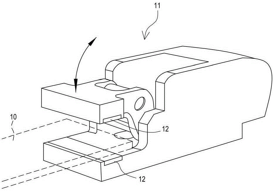
[0004] On the other hand, in the process of conveying and heating the plate blank, as mentioned above, the ambient temperature is generally used to maintain or heat the plate blank, such as figure 1 As shown, a pair of clamps 11 are applied to the plate stock 10 (the pair of clamps have two groups of identical structures, and figure 1 Only the clamp 11 on one side is shown in the figure), after being clamped up and down on both sides of the blank 10 of the plate, it is transported to the machine tool for the next processing procedure, and two clamps 11 can be applied at the same time The entire piece of resistance heating element 12 heats the plate blank 10 held by it, or uses the radiation heating method of the temperature of the conveying environment to heat the plate blank 10. However, the heating speed in the future has Its limit cannot reach the required temperature range in a very short period of time, because it requires a long transportation and heating space and time, which affects the manufacturing schedule
Furthermore, the above-mentioned known heating method is still for the overall heating of the plate blank, so even in a specific process, if only a local area of ​​the plate blank needs to be heated, it still needs to be heated. It is a waste of time to follow the procedure of heating the entire panel blank, which is quite inconsistent with the time cost of production

Method used


Image

  • Plate local heating device and heating method thereof
  • Plate local heating device and heating method thereof
  • Plate local heating device and heating method thereof

Examples


Embodiment Construction

[0064]The present invention will be further described below in conjunction with the accompanying drawings and specific embodiments, so that those skilled in the art can better understand the present invention and implement it, but the examples given are not intended to limit the present invention.

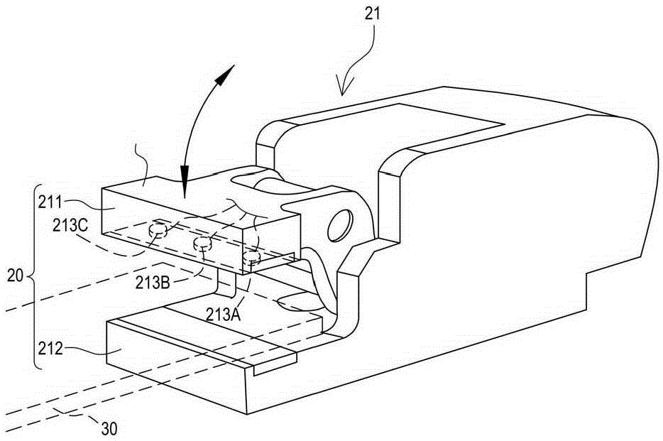
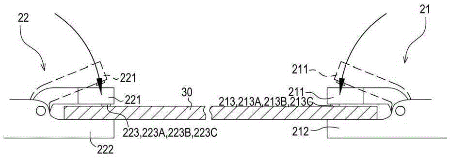
[0065] First, please refer to figure 2 , Figure 3a As shown, the heating device 20 of this embodiment is applied to a material of the plate 30 type, and the material of the plate 30 must be a conductive material capable of passing electric current. The structure of the heating device 20 in this embodiment includes: a first fixture 21 , a second fixture 22 , an electric power system 23 and a power supply control unit 24 . The first clamp 21 has an upper gripping portion 211 and a lower gripping portion 212 for clamping or releasing one side edge of the plate 30 from the upper and lower directions, the upper gripping portion 211 and / or the lower gripping portion 212 A plurality o...


PUM


Abstract

The present invention discloses a plate local heating device and a heating method thereof. The structure of the heating device comprises a first fixture, a second fixture, an electric power system and a power supply control unit. The first fixture is provided with upper and lower clamping devices or an upper holding part and a lower holding part for releasing a plate edge. A plurality of positive electrode terminals are arranged in a region of the upper holding part and the lower holding part in contact with the plate surface. The second fixture is also provided with the upper and lower clamping devices and the upper holding part and the lower holding part for releasing the plate edge. A plurality of negative electrode terminals are arranged in a region of the upper holding part and the lower holding part in contact with the plate surface. The electric power system is used for supplying the power. The power supply control unit is electrically connected with the positive electrode terminals, the negative electrode terminals and the electric power system for supplying power to one of the corresponding positive electrode terminals and one of the negative electrode terminals respectively according to a heating path signal.

Description

technical field [0001] The invention relates to a resistance heating technology of a plate, in particular to a local heating device and a local heating method for a plate directly using the plate as a resistance. Background technique [0002] The use of high-tensile steel sheets in car body sheet metal is increasing rapidly. Because the mechanical properties of high-tensile steel sheets are very different from ordinary steel sheets, the strength of the material increases and the stamping formability decreases, resulting in forming problems. Therefore, the bottlenecks encountered in the cold stamping of high-tensile steel plates are as follows: the formable range of high-tensile steel plates is narrow; the formability is poor, and it is easy to break; The tonnage of stamping equipment is large. In order to improve the stretch formability and reduce springback of high-tensile steel sheets, it is effective to perform hot stamping after heating the plate, and the hot stamping f...

Claims


Application Information

Patent Timeline
IPC IPC(8): B21D37/16
CPCB21D37/16
Inventor 林栢村郭峻志杨正钰
Owner NAT KAOHSIUNG UNIV OF SCI & TECH
Learn More