
A welding machine for welding copper pins and adapters and its resistance welding process

A technology for adapters and welding machines, applied in resistance welding equipment, welding equipment, connections, etc., can solve the problems of poor welding effect, unguaranteed product quality, inconvenient large-scale and batch production, etc.

Active Publication Date: 2020-03-17
HERON INTELLIGENT EQUIP CO LTD
View PDF9 Cites 0 Cited by
  • Summary
  • Abstract
  • Description
  • Claims
  • Application Information

AI Technical Summary

Problems solved by technology

[0002] Traditionally, when riveting the copper pin of the power supply and the adapter, it is necessary to punch the adapter first, then pass the copper pin through the punching hole on the adapter, and finally use the cold forging process to make it The end of the copper pin is deformed and then riveted. The operation steps of this riveting process are not only very cumbersome, it is not convenient for large-scale and mass production, but it also makes the copper pin and the adapter easy to loosen, and the welding is not easy. Strong, poor welding effect, the quality of the product cannot be guaranteed, and the yield rate of the product is low

Method used


Image

  • A welding machine for welding copper pins and adapters and its resistance welding process
  • A welding machine for welding copper pins and adapters and its resistance welding process
  • A welding machine for welding copper pins and adapters and its resistance welding process

Examples


Embodiment Construction

[0020] In order to facilitate the understanding of the present invention, the present invention will be described more fully below with reference to the associated drawings. Preferred embodiments of the invention are shown in the accompanying drawings. However, the present invention can be embodied in many different forms and is not limited to the embodiments described herein. On the contrary, the purpose of providing these embodiments is to make the disclosure of the present invention more thorough and comprehensive.

[0021] Unless otherwise defined, all technical and scientific terms used herein have the same meaning as commonly understood by one of ordinary skill in the technical field of the invention.

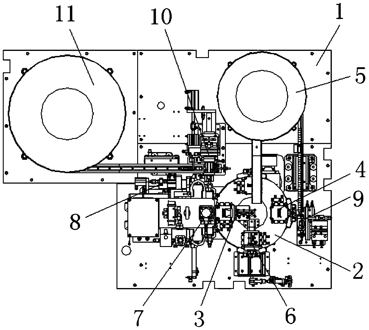
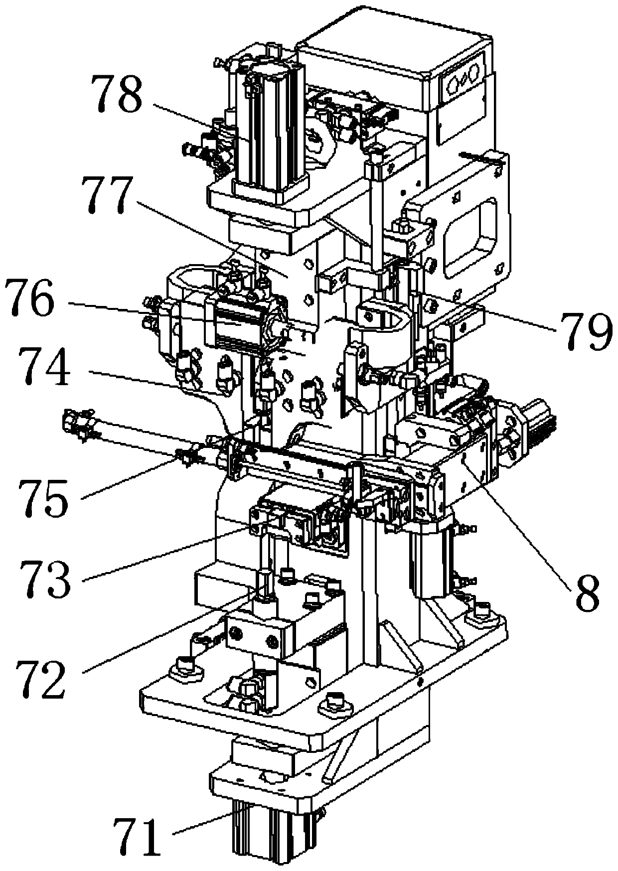
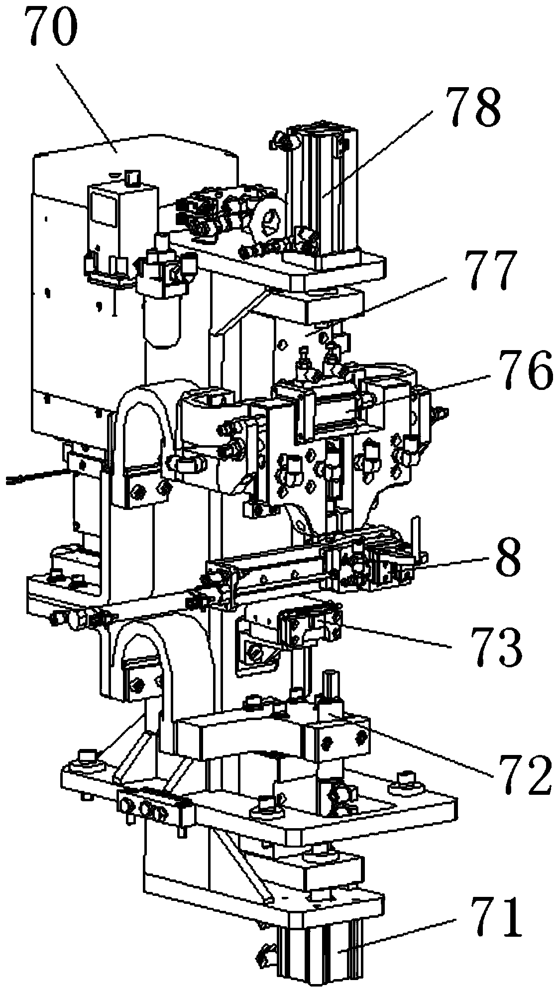
[0022] In this example, refer to Figure 1 to Figure 8 As shown, a terminal block socket bracket welding machine of the present invention includes a workbench 1, a turntable 2 is arranged on the workbench 1, a welding centering mechanism 3 is arranged on the left end of...


PUM


Abstract

The invention discloses a welding machine for welding a copper plug and an adapter and a resistance welding technology of the welding machine. The welding machine comprises a workbench, a rotating disc, a welding centering mechanism, a workpiece positioning tool jig, an adapter feeding vibration disc, a finished product discharge and sorting mechanism, a clamping welding mechanism, a copper inserting needle feeding mechanism, an adapter feeding mechanism, a copper inserting needle conveying mechanism and a copper inserting needle feeding vibration disc. The resistance welding technology is adopted to replace a traditional riveting technology and can carry out convex point welding on a convex point at the end of an inserting needle and the adapter, the inserting needle and the adapter are molten through the resistance welding technology to achieve permanent connection, the welding effect is good, welding is firm, the welding efficacy is high, the phenomenon that the copper inserting needle and the adapter are likely to be loosened after being welded is avoided, it is ensured that product welding is firm, quality is high and the yield is high, and the problems that the traditional riveting technology comprises complex production steps, and is long in production cycle and poor in welding quality are solved.

Description

technical field [0001] The invention relates to a welding machine for welding copper pins and adapters and a resistance welding process thereof. Background technique [0002] Traditionally, when riveting the copper pin of the power supply and the adapter, it is necessary to punch the adapter first, then pass the copper pin through the punching hole on the adapter, and finally use the cold forging process to make it The end of the copper pin is deformed and then riveted. The operation steps of this riveting process are not only very cumbersome, it is not convenient for large-scale and mass production, but it also makes the copper pin and the adapter easy to loosen, and the welding is not easy. Strong, poor welding effect, the quality of the product cannot be guaranteed, and the yield rate of the product is low. Contents of the invention [0003] The technical problem to be solved by the present invention is to provide a welding machine for welding copper pins and adapters ...

Claims


Application Information

Patent Timeline
Patent Type & Authority Patents(China)
IPC IPC(8): B23K11/00B23K11/14B23K11/36H01R43/02
CPCB23K11/00B23K11/002B23K11/14B23K11/36H01R43/02H01R43/0214
Inventor 邹春芽
Owner HERON INTELLIGENT EQUIP CO LTD
Learn More