A ground truss pin shaft connection node structure

A technology for connecting nodes and trusses, applied in building components, building structures, buildings, etc., can solve the problems of inability to carry out structure, cushioning, and inability to increase support span, and achieve the effect of ensuring structural stability and increasing support span.

Inactive Publication Date: 2019-11-29
中建联投建设发展有限公司
View PDF2 Cites 0 Cited by
  • Summary
  • Abstract
  • Description
  • Claims
  • Application Information

AI Technical Summary

Problems solved by technology

This invention can eliminate internal forces such as stress and bending moments transmitted from the structure to the nodes; however, it cannot perform structural cushioning, and cannot increase the support span according to the height of the structure

Method used


Image

  • A ground truss pin shaft connection node structure
  • A ground truss pin shaft connection node structure
  • A ground truss pin shaft connection node structure

Examples


specific Embodiment approach 1

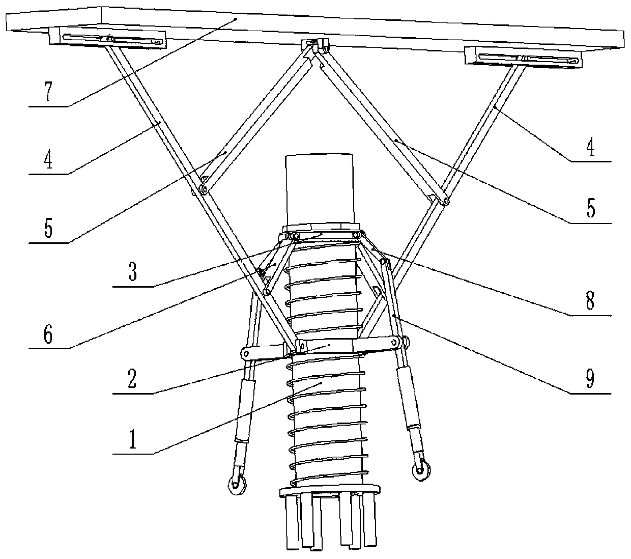
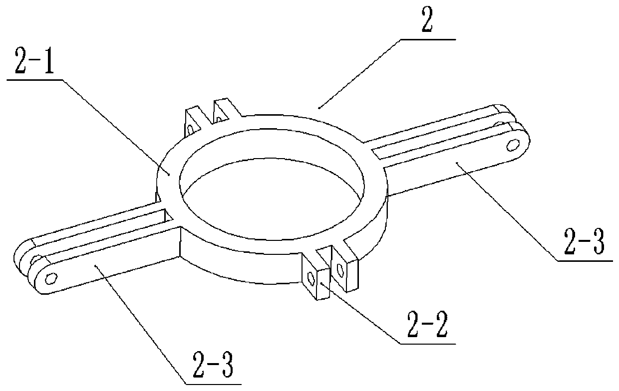
[0026] Combine below figure 1 , 2 , 3, 4, 5, 6, and 7 illustrate this embodiment, a floor truss pin shaft connection node structure, including a floor kingpin 1, a middle sliding sleeve 2, an adjusting screw sleeve 3, a truss side bar 4, a reinforcing bar 5, Adjust the support rod 6 and the top frame 7, the middle sliding sleeve 2 is slidably connected to the middle end of the landing kingpin 1, and the adjusting screw sleeve 3 is connected to the upper end of the landing kingpin 1 through thread fit, and the landing kingpin 1 Spring I and Spring II are sleeved on the top, and the spring I and spring II are respectively located at the upper and lower ends of the middle sliding sleeve 2, and the front and rear ends of the middle sliding sleeve 2 are respectively hingedly connected with the lower end of a truss side bar 4, The upper ends of the two truss side bars 4 are respectively slidably hinged to the left and right ends of the top frame 7, the middle end of the top frame 7...

specific Embodiment approach 2

[0028] Combine below figure 1 , 2 , 3, 4, 5, 6, and 7 illustrate this embodiment, and this embodiment will further explain Embodiment 1. The two reinforcing rods 5 are respectively parallel to the two adjusting struts 6, so as to ensure that the two reinforcing rods 5 force balance.

specific Embodiment approach 3

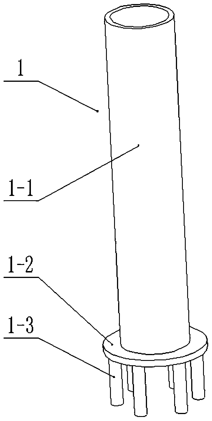
[0030] Combine below figure 1 , 2 , 3, 4, 5, 6, and 7 illustrate this embodiment, and this embodiment will further describe Embodiment 1. The ground kingpin 1 includes a pin tube 1-1, a base 1-2 and a plurality of buried rods 1- 3. The base 1-2 is fixedly connected to the lower end of the pin tube 1-1, and the lower end of the base 1-2 is fixedly connected to a plurality of buried rods 1-3, and the spring II is located between the base 1-2 and the Between the sliding sleeves 2; by embedding a plurality of buried rods 1-3 into the ground, the landing kingpin 1 is fixed.


PUM


Abstract

The invention relates to a truss connection structure, more specifically a floor truss pin shaft connection node structure, including a floor kingpin, a middle sliding sleeve, an adjusting screw sleeve, a truss side bar, a reinforcing bar, an adjusting support bar and a top frame , the middle sliding sleeve is slidably connected to the middle end of the floor kingpin, and the adjusting screw sleeve is connected to the upper end of the floor kingpin through thread fit, and spring I and spring II are sleeved on the floor kingpin, and the spring I and spring II are respectively located at the upper and lower ends of the middle sliding sleeve, and the left and right ends of the middle sliding sleeve are respectively hingedly connected with the lower end of a truss side bar. The invention can adjust the height of the top frame by adjusting the screw sleeve; through the middle sliding sleeve, spring I and spring II, the force of the top frame can be cushioned; by pushing and pulling the connecting rod and the elastic support rod, the top frame can be raised The support span of the elastic support rod is increased at the same time, so as to ensure the stability of the structure.

Description

technical field [0001] The invention relates to a truss connection structure, in particular to a ground truss pin shaft connection node structure. Background technique [0002] For example, the patent application number is CN201510984907.0, a ground truss pin connection node structure, which includes a connecting bracket and a pre-embedded steel plate. The connecting bracket includes a main chord, a top plate, a web and a bottom plate. The top plate is herringbone bent The plate includes a first connecting portion and a second connecting portion connected in sequence, the main chord includes a first chord and a second chord, and the first chord and the second chord are respectively perpendicular to and fixed to the first The top of the connecting part and the second connecting part, the web is fixed between the top plate and the bottom plate, the lower end of the bottom plate is provided with a first connecting piece extending vertically downward along its end surface, and t...

Claims


Application Information

Patent Timeline
Patent Type & Authority Patents(China)
IPC IPC(8): E04B1/38E04B1/98
CPCE04B1/38E04B1/98E04B1/388
Inventor 杨久峰
Owner 中建联投建设发展有限公司
Why Eureka
Try Eureka