
Localized jet soldering device and partial jet soldering method

A soldering and partial technology, which is applied in the field of local jet soldering devices, can solve the problems of molten solder easy to move up and down, broken, leakage, etc.

Active Publication Date: 2012-02-29
SENJU METAL IND CO LTD
View PDF8 Cites 13 Cited by
  • Summary
  • Abstract
  • Description
  • Claims
  • Application Information

AI Technical Summary

Problems solved by technology

[0015]ii. In order to solve the problem i, it is considered to reduce the rotation speed of the screw pump as shown in Patent Document 3 to reduce the pressure when the molten solder is sent out, but When the rotation speed of the pump is reduced excessively, there are problems such as: the pressure to supply molten solder to multiple nozzles and the balance of pressure applied to all nozzles are broken, the height of molten solder ejected from the nozzles is unstable, and the pressure from the nozzles The ejected molten solder moves up and down easily
[0016] iii. Even if the output of the pump is slightly misadjusted, there are problems such as: molten solder is ejected from the nozzle, or molten solder enters the socket insertion hole inside the connector and causes poor contact and the connector cannot be used, Or solder adheres to the surface of the printed circuit board, causing leakage between wirings and causing problems.
[0017] iv. It is considered that the dummy nozzle as shown in Patent Document 2 has the function of adjusting the discharge amount of molten solder, but if no improvement is made to the dummy nozzle shown in Patent Document 2, it is impossible to obtain a satisfactory belt nozzle. Dummy nozzle with output adjustment function
[0018]By the way, the dummy nozzle described in Patent Document 2 does not disclose the content of adjusting the discharge amount of molten solder by using it. The dummy nozzle of Document 2 adjusts the ejection amount of molten solder. Compared with other arbitrary soldering nozzles, the solder ejection area of ​​the opening part of the dummy nozzle is narrow. Due to the structure of the dummy nozzle, it is not possible to adjust the discharge amount of molten solder.

Method used


Image

  • Localized jet soldering device and partial jet soldering method
  • Localized jet soldering device and partial jet soldering method
  • Localized jet soldering device and partial jet soldering method

Examples


Embodiment Construction

[0040] It is an object of the present invention to provide a method for locally stabilizing the component mounting member without reducing the rotational speed of the pump that is difficult to set in the solder tank, even when a nozzle with a small discharge opening is used on the local jet flow solder tank. A local jet soldering device and a local jet soldering method for ejecting molten solder efficiently.

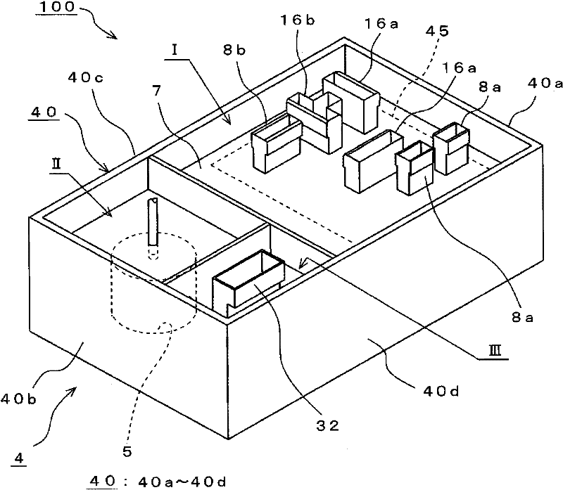
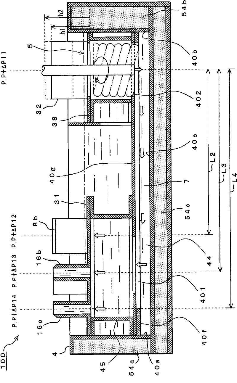
[0041] The second nozzle of the present invention may also be arranged on the nozzle plate together with the first nozzle, but in addition to the nozzle plate, for example, it is arranged near the pump to obtain a more compact partial jet flow solder tank.

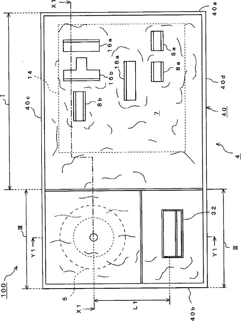
[0042] Hereinafter, the local jet soldering device and the local jet soldering method of the present invention will be described with reference to the drawings. figure 1 The shown local jet flow automatic soldering apparatus 100 is an apparatus for locally applying molten solder 7 to a component mounting member to so...


PUM


Abstract

Even when a nozzle with a small aperture is used in a localized jet solder tank, molten solder can be jetted locally and stably into a component mounted member, without lowering the rotational frequency of a pump in said localized jet solder tank which is difficult to set. As shown in figure 3, the localized jet automatic soldering device (100) is provided with a solder tank (4), which has a nozzle base (44) and contains molten solder (7); a pump (5), which brings the molten solder (7) in the solder tank (4) to a predetermined pressure, and supplies said solder (7) to the nozzle base (44); a plurality of nozzles (8a, etc.) with a predetermined solder ejection area connected to the nozzle base (44), and which eject the molten solder (7) supplied by the pump (5) at a predetermined pressure,such that said solder (7) builds up due to surface tension; and a dummy nozzle (32) connected to the nozzle base (44) with a solder ejection area larger than that of said nozzles (8a, etc.), and which ejects molten solder (7) supplied by the pump (5) at a predetermined pressure. The dummy nozzle (32) is disposed at a location closer to the pump (5) than the abovementioned nozzles (8a, etc.).

Description

technical field [0001] The present invention relates to a local jet soldering device and a local jet soldering device which can be applied to a local jet automatic soldering device for soldering printed circuit boards and electronic components by jetting molten solder only to necessary parts of a printed circuit board. Soldering method. Background technique [0002] Conventionally, an automatic soldering apparatus has been used for soldering electronic components to printed circuit boards. According to the automatic soldering apparatus, a flux applicator (fluxer), a preheater, a jet flow solder tank, a cooling machine, etc. are arranged at predetermined positions, and are comprised. In this automatic soldering device, when soldering electronic components on a printed circuit board, flux is applied to the entire back surface of the printed circuit board with a flux applicator, the printed circuit board is preheated with a preheater, and the printed circuit board is preheated...

Claims


Application Information

Patent Timeline
Patent Type & Authority Applications(China)
IPC IPC(8): H05K3/34B23K1/00B23K1/08B23K3/06B23K101/42
CPCB23K1/085B23K3/0653H05K3/3415H05K3/3447H05K3/3468H05K2203/0746H05K2203/0763B23K2101/42
Inventor 佐藤一策高口彰
Owner SENJU METAL IND CO LTD
Learn More