Door closer

A technology of door closers and shells, which is applied in the direction of wing closers, door/window accessories, wing openers, etc., which can solve problems such as difficult maintenance, short service life, and inconvenient installation of door closers, and achieve adjustable The effect of spring elasticity, simple structure and convenient operation

Pending Publication Date: 2018-08-17
DONGGUAN SHINE GLASS CO LTD
View PDF5 Cites 1 Cited by
  • Summary
  • Abstract
  • Description
  • Claims
  • Application Information

AI Technical Summary

Problems solved by technology

The above-mentioned spring is accommodated and positioned inside the housing of the door closer, and the door closer needs to be respectively fixed to the rotating body and the fixed frame, and at the same time, it needs to meet the requirement of enabling the spring to be deformed under force. Many conditions have led to the current Door closers are very inconvenient to install
[0004] In addition, when the elasticity of the spring decreases after a certain period of use, the automatic return effect of the door and window will be weakened. However, the current door closers have no relevant structure to deal with this phenomenon, and can only be disassembled and replaced when the spring is close to failure. , short service life, difficult maintenance

Method used


Image

  • Door closer
  • Door closer
  • Door closer

Examples


Embodiment Construction

[0025] The preferred embodiments of the present invention will be described below in conjunction with the accompanying drawings.

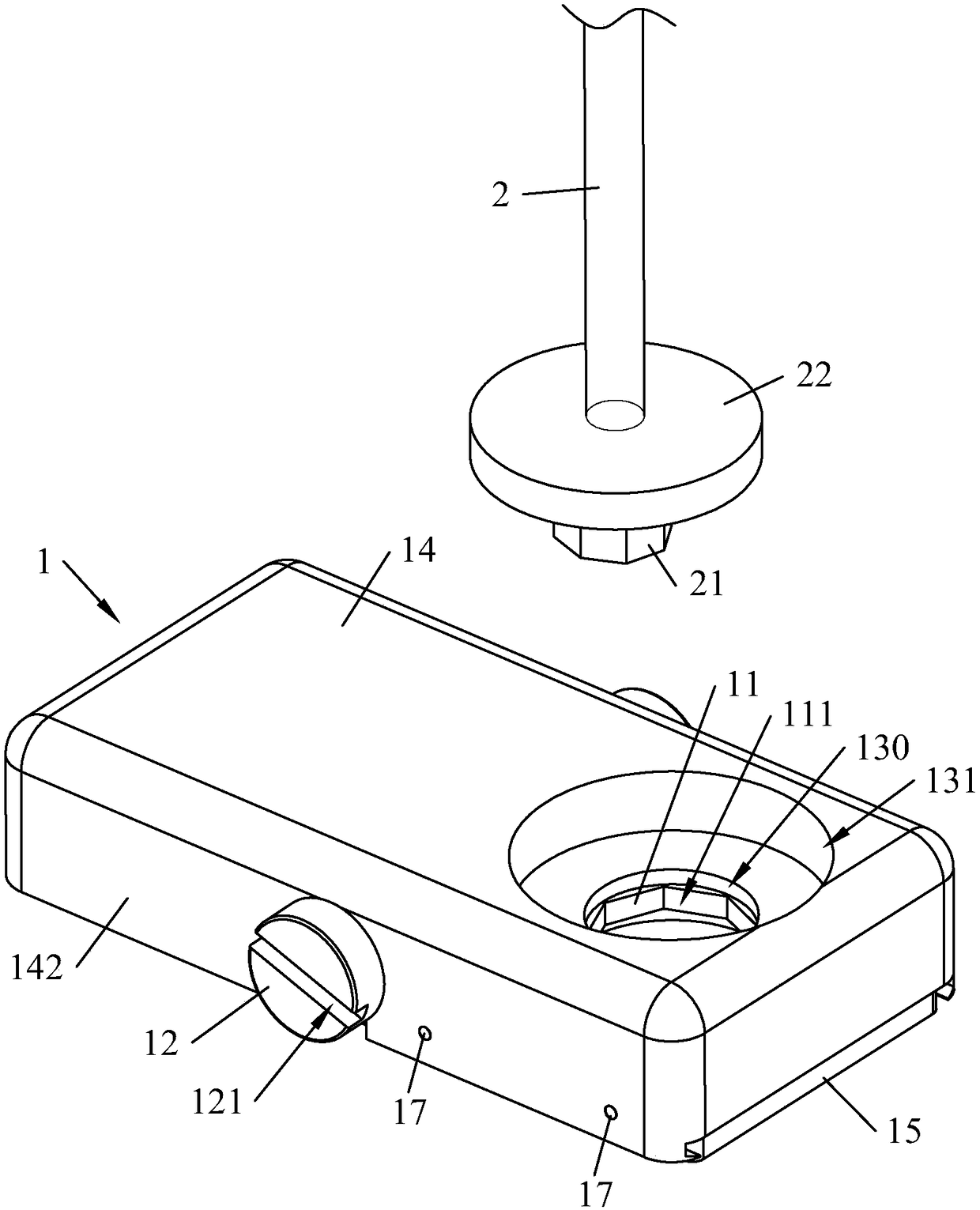
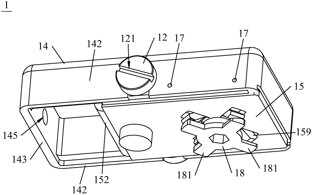
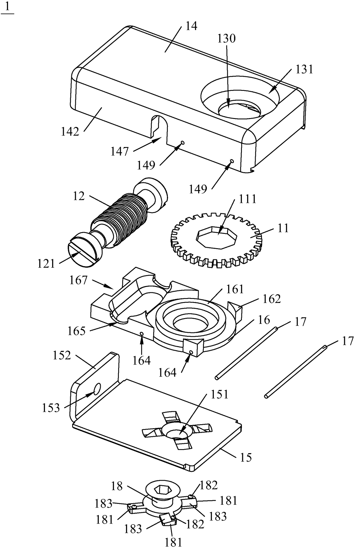
[0026] Such as Figure 1 to Figure 3 As shown, the present invention provides a door closer, comprising a lower assembly 1 and a torsion spring 2, the torsion spring 2 is a linear torsion spring 2 with a longer length and more turns (indicated directly by a straight line in the figure), and the lower assembly 1 includes a housing and a gear 11 and a pinion 12 positioned in the housing and meshing with each other. The gear 11 rotates around a substantially vertical axis, while the rotation axis of the gear shaft 12 is substantially horizontal. The end of the gear shaft 12 is exposed outside the housing, and the gear 11 is provided with a positioning hole 111 . The top of the housing offers an opening 130 that exposes the positioning hole 111. The upper end of the torsion spring 2 is a fixed end, and the lower end of the torsion spring 2 is fixed wi...


PUM


Abstract

The invention discloses a door closer comprising a lower assembly and a torsional spring. The lower assembly comprises a shell and further comprises a gear and a gear shaft which are positioned in theshell. The gear is provided with a positioning hole, and an opening exposed of the positioning hole is formed in the top of the shell. The upper end of the torsional spring serves as a fixing end, abutt joint is fixed to the lower end of the torsional spring and inserted into the positioning hole through the opening, and the butt joint and the gear are positioned circumferentially. The lower assembly and the torsional spring can be fixed to a frame and a rotating body correspondingly; then the butt joint is inserted into the positioning hole to enable the lower end of the torsional spring tobe positioned; when the rotating body is pushed to rotate, the torsional spring rotates along with the rotating body and accumulates force; and after the rotating body is released, the torsional spring drives the rotating body to return to the initial position, and thus automatic closing of a door and a window is achieved. The door closer is simple in structure and convenient to mount. In addition, the shell of the lower assembly is further internally provided with the gear shaft engaged with the gear, the gear shaft can drive the gear to rotate through rotating of the exposed end of the gearshaft, then the butt joint is rotated to enable the lower end of the torsional spring to be twisted, and the effect that elastic force of the spring can be adjusted is achieved.

Description

technical field [0001] The invention relates to a door closer, in particular to a door closer with simple structure and convenient installation. Background technique [0002] In many situations in daily life, some doors and windows need to be kept closed, such as the door of a reading room in a library that needs to be isolated from external interference, or the door of a storage cabinet for storing frozen food in a supermarket. In order to realize the automatic return of these doors and windows, the hydraulic damping return device installed between the rotating body (referring to the door or window) and the fixed frame (the door frame or window frame corresponding to the door or window) was generally used in the past. This device can realize the slow return of the rotating body, and the effect is remarkable, but its manufacturing cost is relatively high, resulting in high prices, which is obviously unfavorable for popularization on some simple doors and windows. [0003] I...

Claims


Application Information

Patent Timeline
Patent Type & Authority Applications(China)
IPC IPC(8): E05F1/10
CPCE05F1/10
Inventor 熊树林
Owner DONGGUAN SHINE GLASS CO LTD
Why Eureka
Try Eureka