Vacuum pipeline joint capable of being rapidly mounted and demounted without tool
A technology of vacuum pipelines and pipeline joints, which is applied in the direction of pipes/pipe joints/fittings, passing components, mechanical equipment, etc., which can solve the problems of complex structure, high price, time-consuming and laborious installation and operation, and achieve low cost and tool-free operation , the effect of changing clothes quickly
- Summary
- Abstract
- Description
- Claims
- Application Information
AI Technical Summary
Problems solved by technology
Method used
Image

Examples
Embodiment 1
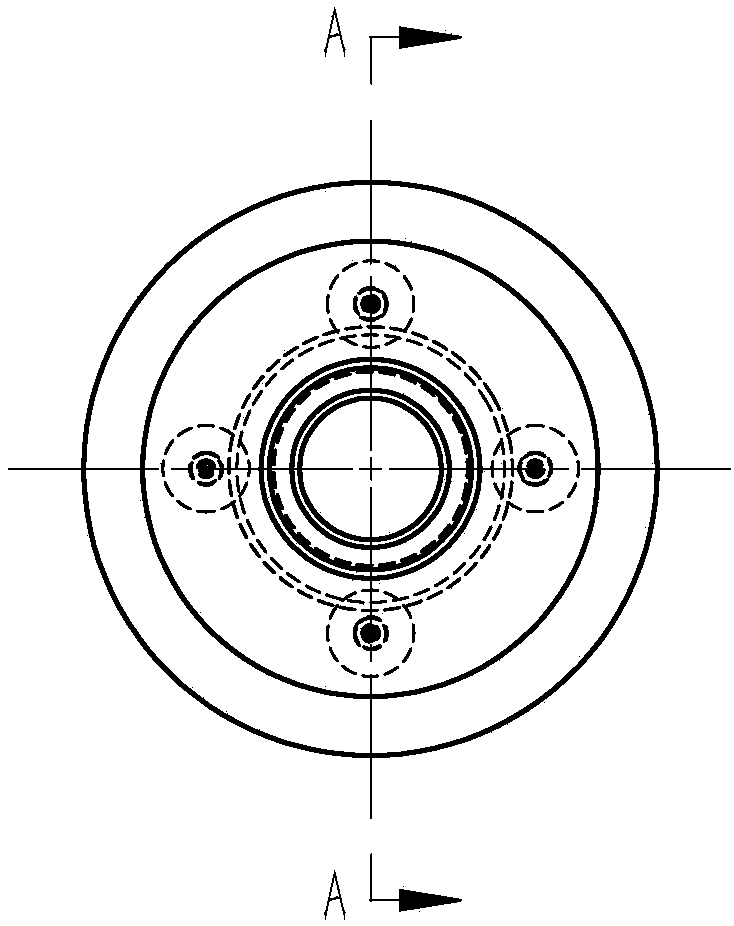
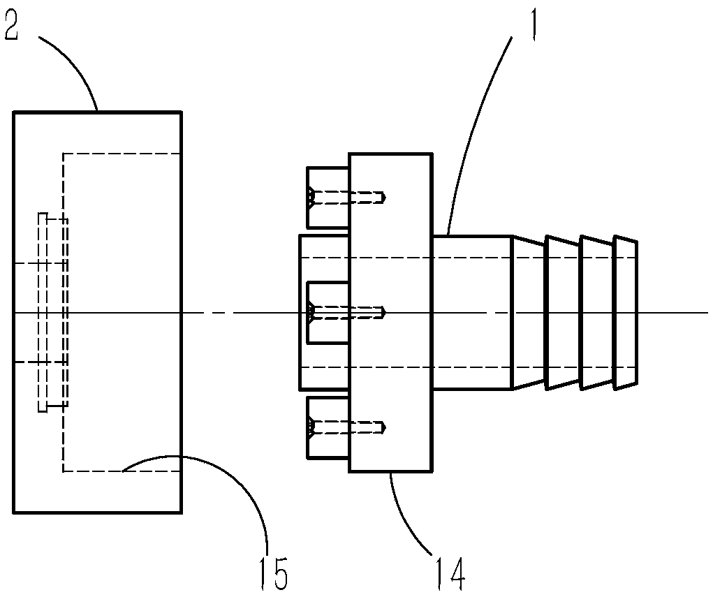
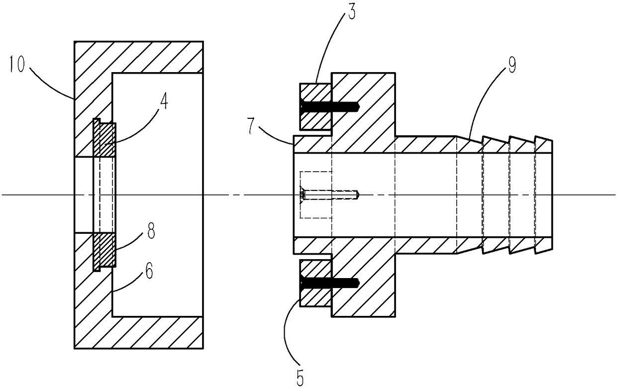
[0044] Such as Figure 1 ~ Figure 3 Shown:
[0045] Tool-free quick installation and removal of the vacuum line connector, characterized by:
[0046]The pipeline joint is composed of a male head 1 and a female head 2, and the male head is provided with four magnetic suction parts 3 (point magnetic suction parts); the female head is provided with a sealing rubber ring 4; the pipeline When the joint is connected, the end face 5 of the magnetic suction part is attracted to the inner end face 6 of the female head, the end face 7 of the male head is in contact with the end face 8 of the sealing rubber ring, and the distance from the end face of the magnetic suction part to the inner end face of the female head is greater than that 2 mm from the end face of the head to the end face of the sealing rubber ring; the other end 9 of the male head is connected to the suction port (not shown) of the vacuum pump through a pipeline (not shown), and the other side 10 of the female head is pr...
Embodiment 2
[0053] Such as Figure 7 ~ Figure 9 Shown:
[0054] Tool-free quick installation and removal of the vacuum line connector, characterized by:
[0055] The pipeline joint is composed of a male head 1 and a female head 2, and the male head is provided with four magnetic suction parts 3 (point magnetic suction parts); the female head is provided with a sealing rubber ring 4; the pipeline When the joint is connected, the end face 5 of the magnetic suction part is attracted to the inner end face 6 of the female head, the end face 7 of the male head is in contact with the end face 8 of the sealing rubber ring, and the distance from the end face of the magnetic suction part to the inner end face of the female head is greater than that 2 mm from the end face of the head to the end face of the sealing rubber ring; the other end 9 of the male head is connected to the suction port (not shown) of the vacuum pump through a pipeline (not shown), and the other side 10 of the female head is p...
Embodiment 3
[0059] Such as Figure 10 ~ Figure 12 Shown:
[0060] Tool-free quick installation and removal of the vacuum line connector, characterized by:
[0061] The pipeline joint is composed of a male head 1 and a female head 2, and the female head is provided with a magnetic suction part 3 (annular magnetic suction part); the female head is provided with a sealing rubber ring 4; the pipeline joint When connected, the end face 5 of the magnetic suction member is attracted to the outer circular surface 11 of the male head, the tapered surface 12 of the male head is in contact with the tapered surface 13 of the sealing rubber ring, and the taper of the male head and the sealing rubber ring are equal; The other end 9 of the male head is connected to the suction port (not shown) of the vacuum pump through a pipeline (not shown), and the other side 10 of the female head is fixed to the outer wall (not shown) of the vacuum box provided with a through hole (not shown) The male head, the fe...
PUM
 Abstract
Description
Claims
Application Information
 - R&D
- Intellectual Property
- Life Sciences
- Materials
- Tech Scout
- Unparalleled Data Quality
- Higher Quality Content
- 60% Fewer Hallucinations
Browse by: Latest US Patents, China's latest patents, Technical Efficacy Thesaurus, Application Domain, Technology Topic, Popular Technical Reports.
© 2025 PatSnap. All rights reserved.Legal|Privacy policy|Modern Slavery Act Transparency Statement|Sitemap|About US| Contact US: help@patsnap.com