Stereoscopic lighting device reducing UGR value

A lighting device and cone technology, which can be applied to lighting devices, fixed lighting devices, components of lighting devices, etc., can solve problems such as poor visual effects of lighting devices

Inactive Publication Date: 2018-08-17
SHANGHAI CAICHENG NEW MATERIAL TECH CO LTD
View PDF0 Cites 5 Cited by
  • Summary
  • Abstract
  • Description
  • Claims
  • Application Information

AI Technical Summary

Problems solved by technology

[0005] The invention provides a three-dimensional lighting device with reduced UGR value, which is used to solve the technical problem of poor visual effect of the anti-glare lighting device in the prior art

Method used


Image

  • Stereoscopic lighting device reducing UGR value
  • Stereoscopic lighting device reducing UGR value
  • Stereoscopic lighting device reducing UGR value

Examples


specific Embodiment 1

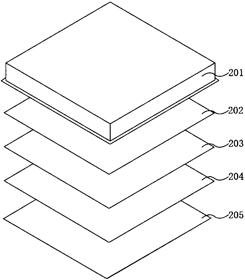
[0063] Such as Figure 11 As shown, the three-dimensional lighting device that can reduce the UGR value provided in the first embodiment of the present invention includes: a panel light source 1101, a reflector 1102 that reflects light, a light guide plate 1103 that converts the side light source into a surface light source and makes the light uniform, Diffusion plate 1104 that uniformizes the overall color and brightness of the light source; a pyramid-shaped microstructure layer 1105 with a unit size of 0.5 mm and a side angle of 30 degrees arranged at 45 degrees; a focal length of PET material with a thickness of 1.5 mm and a refractive index of 1.575 layer 1106 , a microlens layer 1107 with a unit size of 0.525 mm and a radius of curvature of 0.2625 mm in a 45-degree array as the base; a surface coating 1108 with a refractive index of 1.3.

[0064] With the above structural design, the pyramid-shaped microstructure pattern can reduce the UGR value to below 19, and at the sa...

specific Embodiment 2

[0065] as Figure 12 As shown, the three-dimensional lighting device that can reduce the UGR value in the specific embodiment of the present invention includes: a panel light source 1201, a reflector 1202 that reflects light, a light guide plate 1203 that converts the side light source into a surface light source and makes the light uniform; A diffuser plate 1204 with uniform color and brightness; a hexagonal pyramid microstructure 1205 with a unit size of 0.5 mm and a side angle of 30 degrees arranged at 60 degrees; a PET material focal length layer 1206 with a thickness of 0.71 mm and a refractive index of 1.575; the unit size The hexagonal-based microlens layer 1207 has a radius of 0.525 mm and a radius of curvature of 0.2625 mm in a 60-degree array.

[0066] With the above structural design, the hexagonal pyramid microstructure pattern can reduce the UGR value to below 19, and at the same time, it can interact with the microlens to present a three-dimensional shading. The ...


PUM

PropertyMeasurementUnit
Thicknessaaaaaaaaaa

Abstract

The invention discloses a lighting device and particularly relates to a stereoscopic lighting device reducing UGR value. The lighting device comprises a panel light source, a reflector, a light guideplate, a diffusion plate and an anti-dazzle plate. The anti-dazzle plate is composed of a microstructure layer, a transparent base plate layer and a micro-lens layer. On one hand, cones arranged in anarray in the microstructure layer enable large-angle light rays given out by the panel light source to generate multi-grade refraction or reflection, and the large-angle light rays are converted intosmall-angle light rays and conduct emergency to the outside finally, and therefore the UGR value of the whole lighting device is lowered. On the other hand, the micro-lens layer can cooperate with the transparent base plate layer and the microstructure layer to enable the light rays given out by the panel light source to show stereoscopic graphic-text information. In this way, due to the anti-dazzle layer, the UGR value of the lighting device can be reduced, the anti-dazzle effect is achieved, and the stereoscopic graphic-text information can be shown; and in this way, the visual effect and the lighting quality are improved, and the decorative fashion sense and science and technology sense are shown.

Description

technical field [0001] The invention relates to the field of display technology, in particular to a three-dimensional lighting device for reducing UGR value. Background technique [0002] UGR (Unified Glare Rating, unified glare value), is a parameter used to measure the subjective response of the light emitted by the lighting device in the indoor visual environment to the uncomfortable feeling of the human eye. The UGR test stipulates that the lighting device is perpendicular to the direction of the ceiling. It is 0 degrees, the direction parallel to the direction of the lighting device and the ceiling is 90 degrees, and the light in the direction of the direction in the range of 65 degrees to 90 degrees will produce glare. At present, some countries in Europe have issued standards for indoor lighting. For example, Germany mandates that lighting devices whose UGR value is less than 19 can be used for indoor lighting. [0003] In the prior art, the diffusion plate in the li...

Claims


Application Information

Patent Timeline
IPC IPC(8): F21S8/00F21V13/00F21V5/04
CPCF21S8/00F21V5/004F21V13/00
Inventor 孙利强姚俊俊
Owner SHANGHAI CAICHENG NEW MATERIAL TECH CO LTD
Why Eureka
Try Eureka