Testing system and method used for simulating sunlight focusing

A test system and sunlight technology, applied in the field of test equipment, can solve the problems that the incident angle of sunlight cannot be adjusted accurately, the range of incident angle of sunlight is limited, and the equipment occupies a large area, so as to reduce the test distance and facilitate The effect of building and reducing the requirements of the test site

Pending Publication Date: 2018-08-17
HASCO VISION TECHNOLOGY CO LTD
View PDF0 Cites 2 Cited by
  • Summary
  • Abstract
  • Description
  • Claims
  • Application Information

AI Technical Summary

Problems solved by technology

[0003] The technical problem to be solved in the present invention is: the existing test system for simulating sunlight focusing, the sunlight incident angle of the sunlight focusing simulation equipment cannot be systematically and accurately adjusted, the range of simulated sunlight incident angles is limited, and the operation is inconvenient And the test effect is poor; at the same time, the equipment occupies a large area, which is not conducive to laboratory testing

Method used


Image

  • Testing system and method used for simulating sunlight focusing

Examples


Embodiment 1

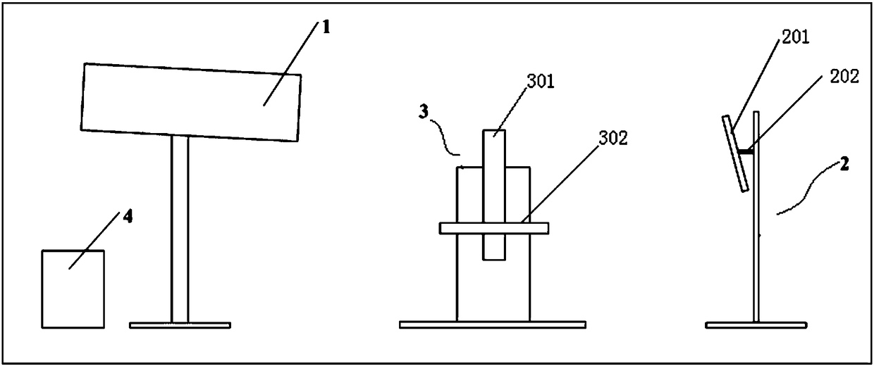
[0020] see figure 1 , a test system for simulating the focus of sunlight, comprising a sunlight simulation device 1, an angle adjustment device 3, and a reflector 2, the three are lined up with a certain distance between them; the angle adjustment device 3 has Rotating shaft 301, rotating shaft 301 is perpendicular to platform 302 and is fixedly connected; Rotating shaft 301 can rotate by itself under the drive of the first power mechanism, and can rotate in the facade under the drive of the second power mechanism, thereby driving platform 302 to rotate, and platform 302 is used for placing and fix the object to be detected; the reflector 2 has an emitting mirror surface 201, and a goniometer 202 is arranged on the reflecting mirror surface, and the reflecting mirror surface 201 receives the illumination of the sunlight simulation device 1 and reflects it onto the object to be detected, and the object to be detected Has a lens structure.

[0021] In this example, see figure ...

Embodiment 2

[0026] The difference from Embodiment 1 is that the rotating shaft 301 can rotate universally under the drive of the second power mechanism, so that the platform 7 and the object to be measured on it can be adjusted with a higher degree of freedom. All the other implementations are the same as in Example One.


PUM


Abstract

The invention relates to a testing system used for simulating sunlight focusing. The testing system comprise a sunlight simulating device, an angle regulating device and a reflector which a lined up at certain intervals and is characterized in that the angle regulating device is provided with a rotary shaft, and the rotary shaft is vertical to a platform and fixedly connected with the same; the rotary shaft can be driven by a first power mechanism to rotate and driven by a second power mechanism to rotate in a vertical plane so as to drive the platform to rotate, and the platform is used for placing and fixing a to-be-test object; the reflector is provided with a reflecting mirror surface, the reflecting mirror surface is provided with an angle meter, the reflecting mirror surface receivesthe light of the sunlight simulating device and reflects the light to the to-be-tested object, and the to-be-tested object is provided with a lens structure. The testing system has the advantages that sunlight irradiation of various incidence angles can be precisely and reliably simulated, and the testing results are allowed to have high repeatability; the system's requirements on testing sites are lowered; the rotation and movement of the angle regulating device are controlled automatically, and the testing process is allowed to be simple and efficient.

Description

technical field [0001] The invention relates to a test system and method for simulating sunlight focusing, and belongs to the technical field of test equipment. Background technique [0002] Motor vehicle headlamps with lens structures have a relatively high market share due to their superior performance in appearance, size and performance. However, due to the structure of the lens itself, sunlight will focus in a certain area (some) after passing through the lens. If the focus area is distributed on a certain (some) structure of the headlight, the surface of the structure will be focused by sunlight And generate high temperature, there is a risk of failure. Moreover, due to the different incident angles of sunlight, the focus position of sunlight after passing through the lens will also be different. In order to evaluate and test possible failures caused by solar focus during the development and design stage of lamps, a complete test system for simulating solar focus is r...

Claims


Application Information

Patent Timeline
Patent Type & Authority Applications(China)
IPC IPC(8): G01M11/04
CPCG01M11/00G01M11/0207G01M11/04
Inventor 王宽沈治国
Owner HASCO VISION TECHNOLOGY CO LTD
Why Eureka
Try Eureka