Automatic planning method for aircraft injection arrangement

An automatic planning and aircraft technology, applied in the direction of instruments, position/direction control, non-electric variable control, etc., can solve the problems of low work efficiency, high labor intensity, high error and omission rate, and achieve the effect of improving work efficiency and accuracy

Active Publication Date: 2018-08-17
中国人民解放军63920部队
View PDF11 Cites 0 Cited by
  • Summary
  • Abstract
  • Description
  • Claims
  • Application Information

AI Technical Summary

Problems solved by technology

This manual-based work mode of design, inspection, and control has the problems of high labor intensity, low work efficiency, and high error and omission rate
During the preparation and impl

Method used


Image

  • Automatic planning method for aircraft injection arrangement
  • Automatic planning method for aircraft injection arrangement
  • Automatic planning method for aircraft injection arrangement

Examples


Example Embodiment

[0028] Example 1

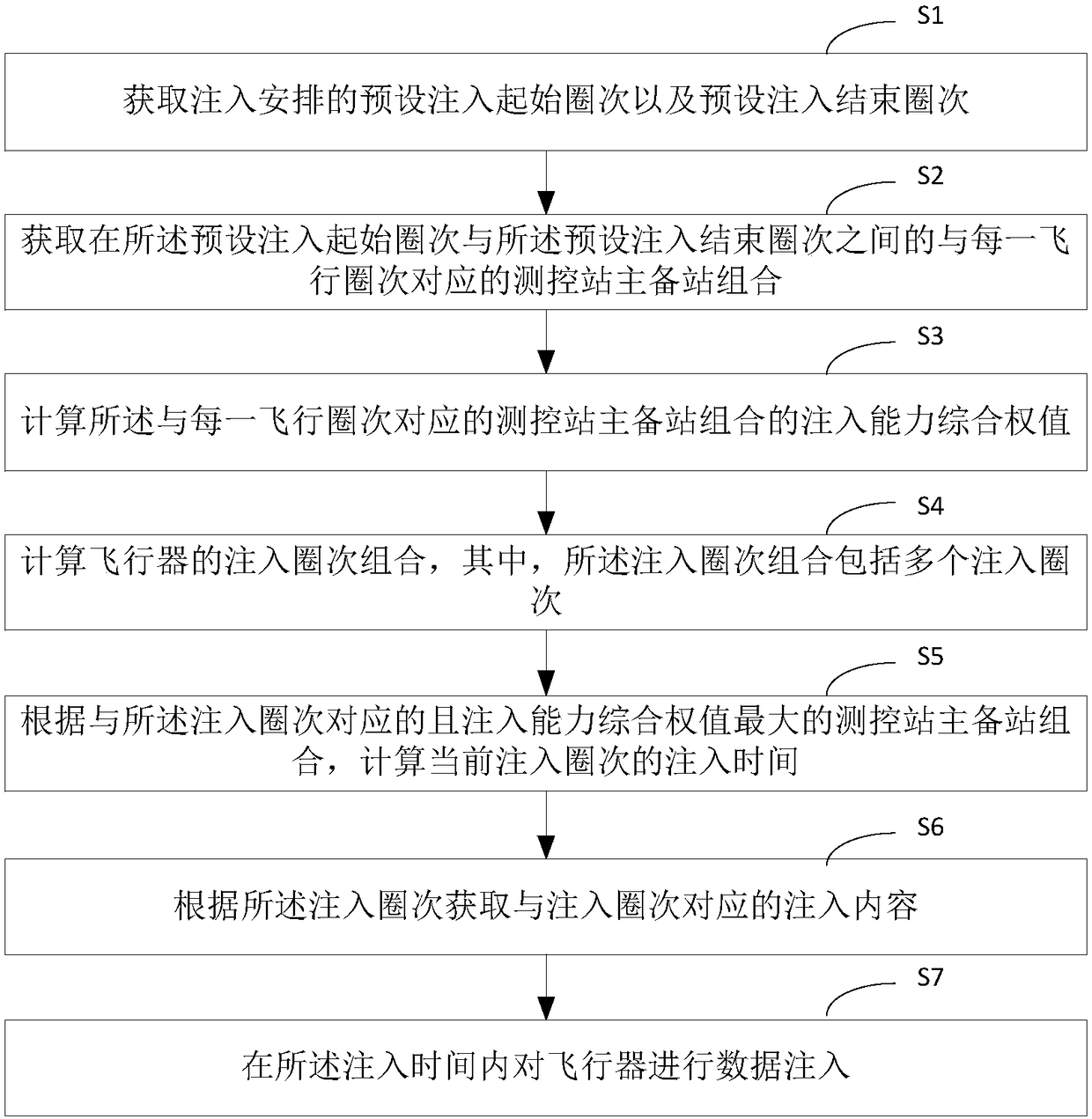
[0029] figure 1 It shows the flow chart of the automatic planning method for aircraft injection arrangement provided by Embodiment 1 of the present invention. The automatic planning method includes: setting the combination of the master and backup stations of the measurement and control station for tracking the aircraft, wherein the combination of the master and backup stations of the measurement and control station includes the master station and the backup station; the master station is used to inject data into the aircraft first, and the backup station is used to inject data into the aircraft when the master station fails to inject data. like figure 1 As shown, the method includes:

[0030] Step S1, obtaining the preset injection start circle and the preset injection end circle of the injection arrangement.

[0031] Step S2, acquiring the combination of master and backup stations of the measurement and control station corresponding to each flight lap b...

Example Embodiment

[0055] Example 2

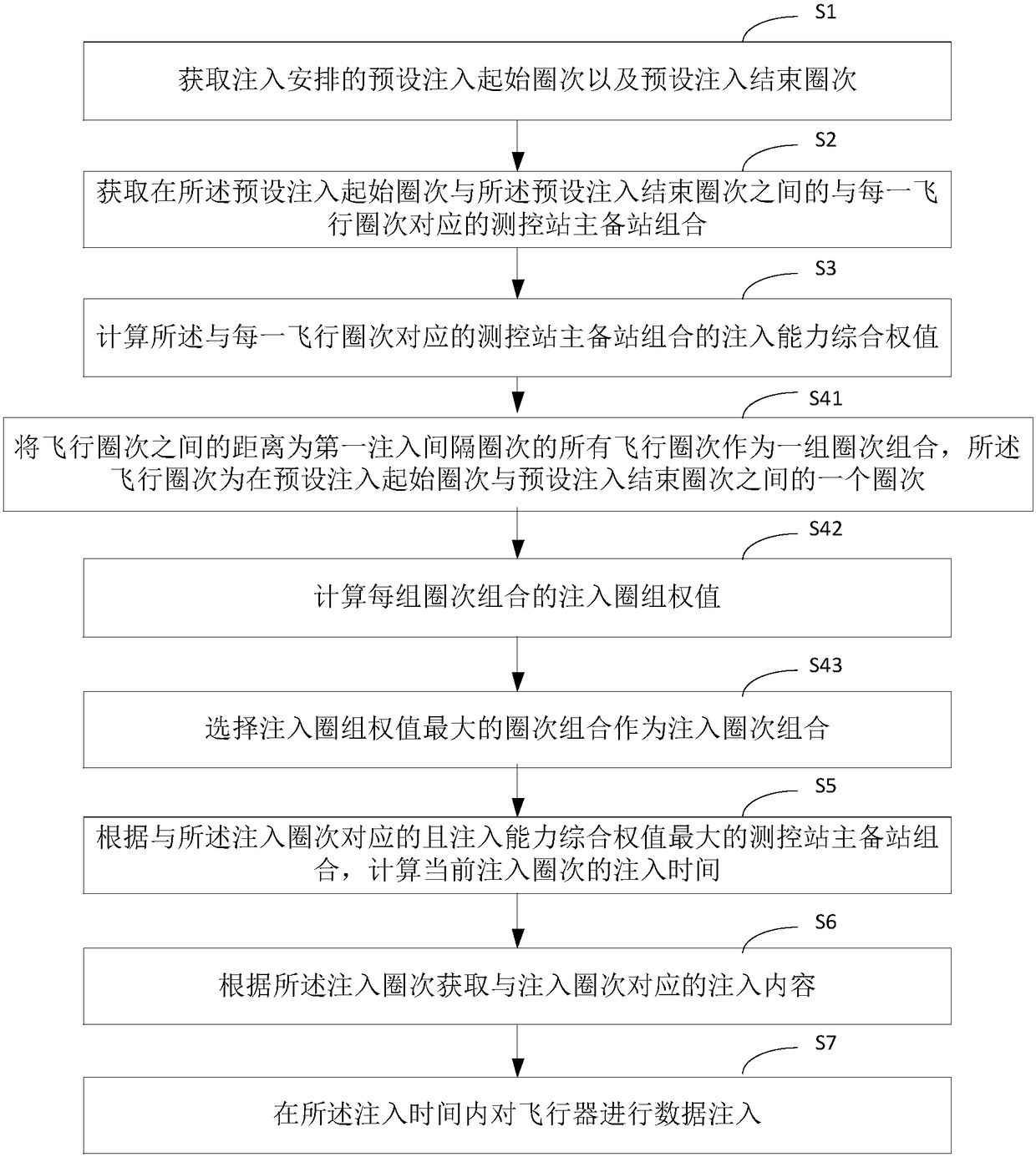
[0056] In this embodiment, step S4 is further limited. figure 2 A flow chart showing an automatic planning method for an aircraft injection arrangement according to Embodiment 2 of the present invention, in figure 2 neutralize figure 1 Steps with the same reference numbers are the same as figure 1 The same text descriptions are applicable and will not be repeated here. In a possible implementation, step S4 includes:

[0057] Step S41, combining all the flight laps whose distance between the flight laps is the first injection interval lap as a group of laps, the flight laps are between the preset injection start lap and the preset injection end lap A circle between times.

[0058] Among them, the first injection interval is the preset first injection interval. If the interval is too small, it will increase the manual operation on the ground and bring operational risks; if the interval is too large, it will increase the number of injection frames and oc...


PUM


Abstract

The invention discloses an automatic planning method for aircraft injection arrangement. The method comprises the following steps that: obtaining a preset starting circle number and a preset injectionending circle number of injection arrangement; obtaining a measurement and control station host and standby station combination corresponding each flight circle number between the preset starting circle number and the preset injection ending circle number; calculating the injection ability comprehensive weight value of the measurement and control station host and standby station combination corresponding each flight circle number; calculating the injection circle number combination of the aircraft, wherein the injection circle number combination comprises a plurality of injection circle numbers; and according to the host and standby station combination which corresponds to the injection circle number and has a maximum injection ability comprehensive weight value, calculating the injectiontime of the current injection circle number. By use of the automatic planning method for the aircraft injection arrangement, the automatic planning of the aircraft injection arrangement is realized,and the working efficiency and the accuracy of the injection arrangement are improved.

Description

technical field [0001] The invention relates to the field of spacecraft measurement control, in particular to an automatic planning method for aircraft injection arrangement. Background technique [0002] In order to realize the control of the aircraft, the ground flight control center guarantees the smooth progress of the aircraft flight test task process by means of injection, and realizes the automation of the aircraft measurement and control process. For example, during the in-orbit operation of the aircraft, the follow-up flight program is injected and updated at regular intervals. The update range and injection volume depend on the command density and tracking measurement and control conditions. The injected content includes measured orbit elements, flight procedures, relay correction parameters, etc. [0003] Injection arrangement planning is a design work that specifies the content, time, and station requirements of spacecraft on-orbit status maintenance and program...

Claims


Application Information

Patent Timeline
IPC IPC(8): G06F17/50G05D1/00
CPCG05D1/00G06F30/20
Inventor 李剑于天一邹雪梅费江涛刘辛胡国林李晓平朱峰登尚德生邓颖丽
Owner 中国人民解放军63920部队
Why Eureka
Try Eureka