Method for determining load distribution rate of straight spur gear double-tooth meshing zone

A spur gear and load distribution technology, which is applied in special data processing applications, instruments, electrical digital data processing, etc., can solve the problems of load distribution rate error, high hardware requirements, poor calculation economy, etc., to improve calculation accuracy, The effect of low hardware requirements and low computational cost

Active Publication Date: 2018-08-17
WUHAN UNIV OF TECH
View PDF3 Cites 7 Cited by
  • Summary
  • Abstract
  • Description
  • Claims
  • Application Information

AI Technical Summary

Problems solved by technology

[0003] At present, there are mainly three research methods on the load distribution ratio between spur gear teeth at home and abroad: (1) finite element method: the load distribution ratio can be accurately calculated by means of the finite element method, which is a relatively widely used method, but often The calculation economy is poor, and a fine finite element mesh model must be established, which is time-consuming to solve; (2) Traditional analytical method: Simplify the relationship of multiple pairs of loaded gear teeth into a spring model connected in parallel, and use the cantilever beam assump

Method used


Image

  • Method for determining load distribution rate of straight spur gear double-tooth meshing zone
  • Method for determining load distribution rate of straight spur gear double-tooth meshing zone
  • Method for determining load distribution rate of straight spur gear double-tooth meshing zone

Examples


Example Embodiment

[0033] In order to make the object, technical solution and advantages of the present invention clearer, the present invention will be further described in detail below in conjunction with the accompanying drawings and embodiments. It should be understood that the specific embodiments described here are only used to explain the present invention, not to limit the present invention.

[0034] A method for determining the load distribution ratio of a double-teeth meshing area of ​​a spur gear, the method comprising the following steps:

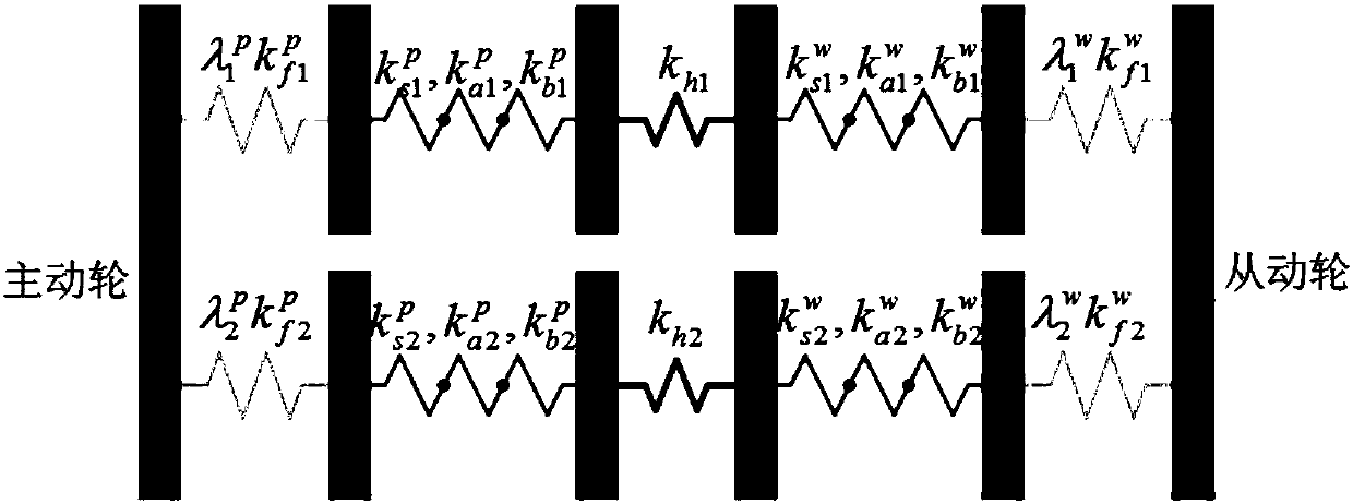
[0035] S1. Design the coupling factor λ(F 1 , F 2 ), F 1 , F 2 are the actual meshing forces on the No. 1 and No. 2 teeth of the driving wheel or the driven wheel in the double-tooth meshing area, respectively,

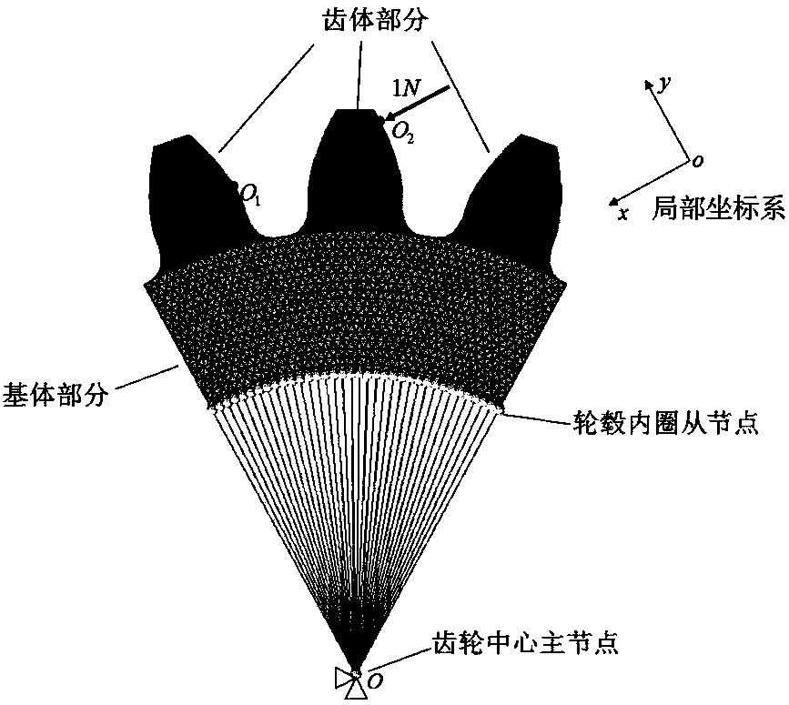
[0036] Specifically, such as Figure 1a , Figure 1b As shown, the gear base stiffness structural coupling factor is equal to the ratio of the gear base stiffness considering the structural coupling effect to the gear base stiffness ...


PUM


Abstract

The invention discloses a method for determining the load distribution rate of a straight spur gear double-tooth meshing zone. The method comprises the following steps that: firstly, obtaining the basic parameters of a driving wheel and a driven wheel; establishing an improved gear meshing rigidity model which considers a structure coupling effect; utilizing a finite element method to determine the structure coupling factor of the basic rigidity of the driving wheel and the driven wheel; on the basis of a minimum potential energy principle, establishing a single-target optimization model whichtakes a tooth surface load as a variable and gear system potential energy as a target function; utilizing a genetic algorithm to solve the optimization model to obtain the tooth surface load; and onthe basis of the tooth surface load, obtaining the load distribution rate of the straight spur gear double-tooth meshing zone. By use of the method, calculation accuracy is greatly improved, the influence of a structure coupling effect, an input moment and a gear geometrical parameter on the load distribution rate can be accurately reflected, calculation cost is low, only a small scale of meshes needs to be adopted to obtain a result of which the error is within an acceptable range, and the method has a low requirement on hardware, is a universal model, and can realize a GUI (Graphical User Interface) operation through computer programming.

Description

technical field [0001] The invention belongs to the field of mechanical analysis of gear structures, and in particular relates to a method for determining the load distribution rate of a double-teeth meshing area of ​​a spur gear. Background technique [0002] Gears are the basic transmission unit of many mechanical structures. Spur gears are widely used in mechanical equipment such as automobile transmissions, industrial robots, and wind power gearboxes because of their simple structure, high transmission efficiency, and strong adaptability. Lightweight design is an important trend in the development of modern mechanical products. In terms of gear design, it is mainly manifested in the small module and heavy load of the gear, which puts forward higher requirements for the check of the gear carrying capacity. Since the spur gear transmission has alternating single and double teeth, in the single-tooth meshing area, the load is borne by a pair of teeth, and in the double-toot...

Claims


Application Information

Patent Timeline
IPC IPC(8): G06F17/50
CPCG06F30/17G06F2119/06
Inventor 华林谢重阳李瑄
Owner WUHAN UNIV OF TECH
Why Eureka
Try Eureka