In-mold quick-changing inductive character code structure device

A character code and sensor technology, which is applied in the field of inductive character code structure devices for quick change in the mold, can solve the problems of large molds, affecting production efficiency, waste of machine use time, etc.

Active Publication Date: 2018-08-21
深圳亿和模具制造有限公司
View PDF6 Cites 0 Cited by
  • Summary
  • Abstract
  • Description
  • Claims
  • Application Information

AI Technical Summary

Problems solved by technology

[0003] With the increasingly fierce competition in global mold technology, the tonnage of molds in the entire field of metal stamping mold technology is increasing, and the coverage of products is also increasing, and the requirements are also strict, especially in large-scale continuous molds and manipulators. In the mold, in order to save mold costs, more and more molds share a set of molds. Because the mold is large, it is difficult to disassemble and assemble, and frequent code changes will directly affect production efficiency. Machine use time is wasted. Calculated with a 1200T punch , one hour is quite expensive, and even more serious will affect the customer's delivery time
[0004] Therefore, this series of problems brings pressure and great trouble to the production, especially in the large-scale continuous mold or manipulator mold of about 2000T, the whole mold must be opened every time the model is changed, and it will be changed if you are not careful. Wrong, such repeated work over and over again seriously delays the operation time of the entire production, and the waste caused by waiting for replacement. For a long time, this problem has formed a vicious circle in the entire production chain, which eventually brings huge losses.

Method used


Image

  • In-mold quick-changing inductive character code structure device
  • In-mold quick-changing inductive character code structure device
  • In-mold quick-changing inductive character code structure device

Examples


Embodiment Construction

[0022] In order to make the purpose, technical solutions and advantages of the embodiments of the present invention clearer, a clear and complete description will be made below in conjunction with the technical solutions in the embodiments of the present invention. Obviously, the described embodiments are part of the embodiments of the present invention, and Not all examples. Based on the embodiments of the present invention, all other embodiments obtained by persons of ordinary skill in the art without making creative efforts belong to the protection scope of the present invention.

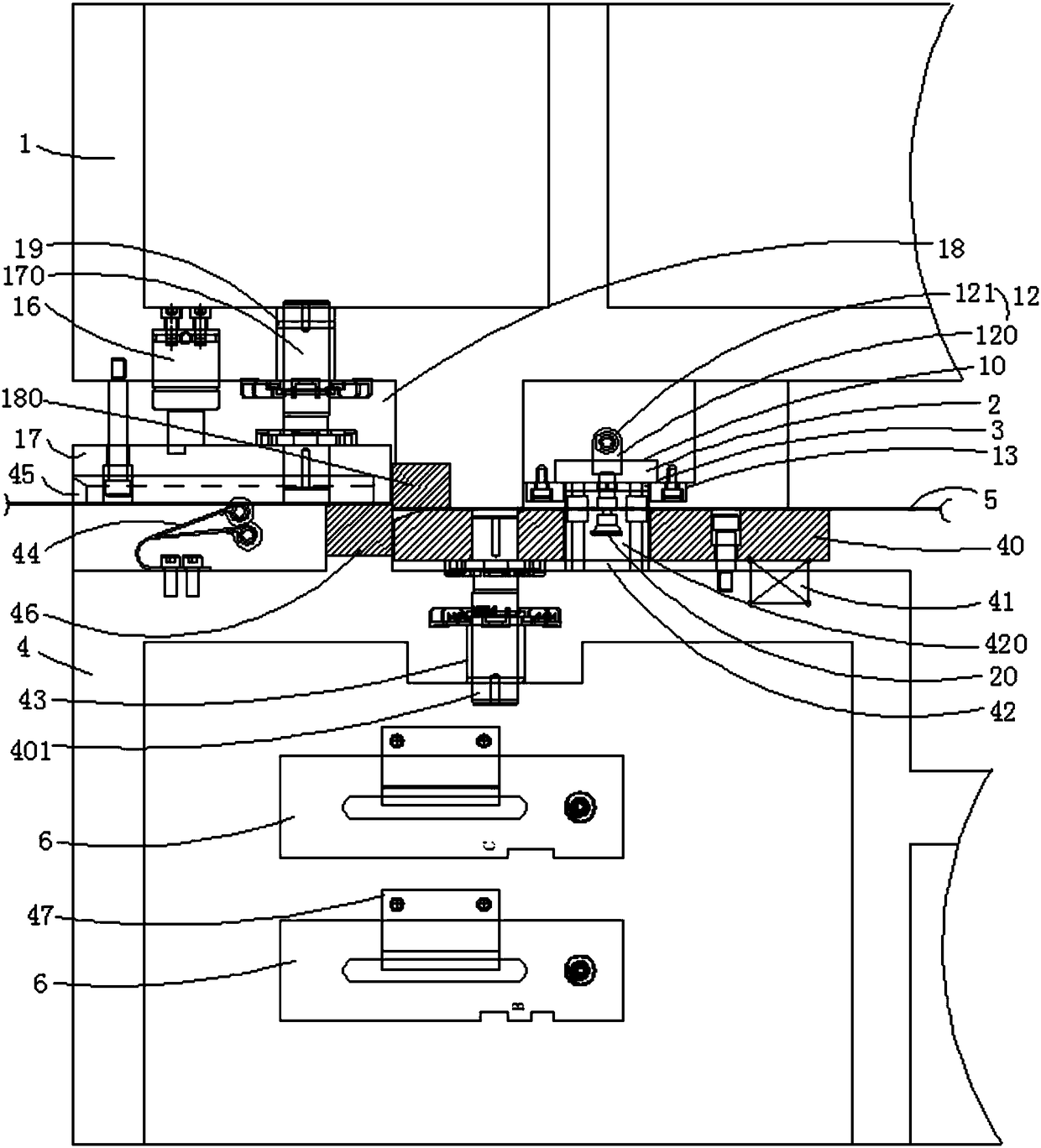
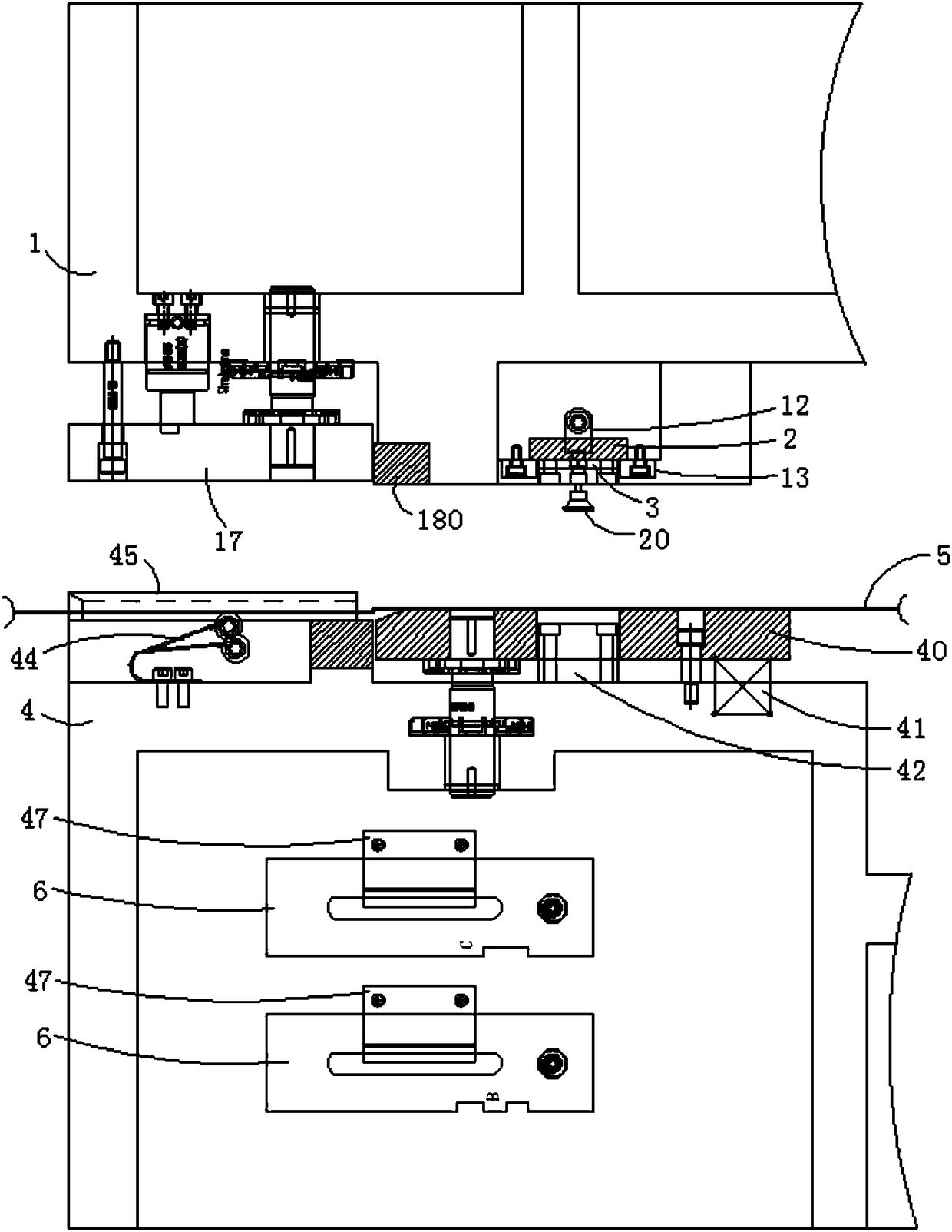
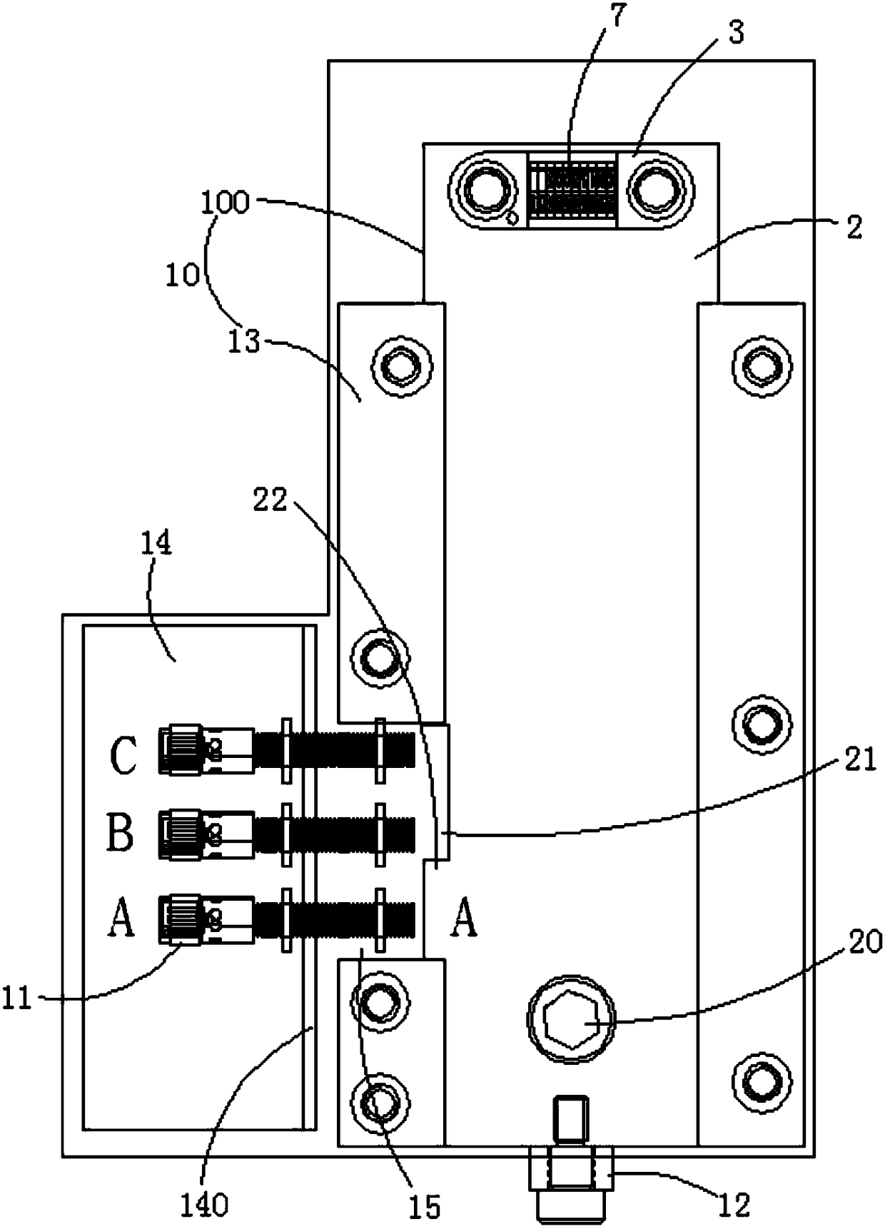
[0023] In the preferred embodiment of the present invention, the inductive code structure device for quick change in the mold is as follows: figure 1 shown, see also figure 2 and image 3 , including the upper mold base 1; also includes the character code drawing plate 2 and the character code base 3 for placing the character code 7; the character code drawing plate 2 and the character code ba...


PUM


Abstract

The invention relates to an in-mold quick-changing inductive character code structure device. The device comprises an upper mold holder and further comprises a character code pulling plate and a character code base for placing character codes; the character code pulling plate and the character code base are detachably connected; a pulling groove corresponding to the character code pulling plate isformed in the upper mold holder, and sensors for sensing the character codes on the character code base after the character code pulling plate is installed into the pulling groove and a locking blockfor locking the character code pulling plate after the character code pulling plate is installed into the pulling groove are arranged on the upper mold holder; in the use, after the character codes are installed on the character code base, the character code base is fixed on the character code pulling plate, the character code pulling plate is pushed in the pulling groove and then locked by the locking block to prevent falling off, the sensors sense the character codes, there is no need to disassemble the entire upper mold from a punching machine for the case of frequently changing product models, character code contents and the like during the mold production process, and replacement efficiency and production waiting time are greatly improved.

Description

technical field [0001] The invention relates to the technical field of large-scale sheet metal dies, stamping dies, automobile dies and other large continuous dies and manipulator dies, and more specifically relates to an in-mold quick-change induction code structure device. Background technique [0002] The mold character code is the letter and sequence number added to each part of the mold in order to identify the mold name, part name, part material, part hardness, or to identify the assembly position of the part on the mold. [0003] With the increasingly fierce competition in global mold technology, the tonnage of molds in the entire field of metal stamping mold technology is increasing, and the coverage of products is also increasing, and the requirements are also strict, especially in large-scale continuous molds and manipulators. In the mold, in order to save the cost of the mold, more and more molds share a set of molds, because the mold is large, difficult to disass...

Claims


Application Information

Patent Timeline
IPC IPC(8): B21D37/00B21C51/00
CPCB21C51/005B21D37/00Y02P90/30
Inventor 李愉愉张耀华谢茂春谢菲
Owner 深圳亿和模具制造有限公司
Why Eureka
Try Eureka