
Locking device and vacuum equipment

A technology of vacuum equipment and locking devices, applied in mechanical equipment, connecting components, etc., can solve the problems of elastic, inconvenient, and insufficiently smooth operation of dimensional precision sealing rings, and achieve the effects of convenient operation, guaranteed vacuum environment, and simple structure

Pending Publication Date: 2018-08-21
SHENZHEN YUANSU OPTOELECTRONICS TECH CO LTD
View PDF0 Cites 1 Cited by
  • Summary
  • Abstract
  • Description
  • Claims
  • Application Information

AI Technical Summary

Problems solved by technology

Due to the problems of dimensional accuracy, assembly accuracy and the elasticity of matching connectors such as sealing rings between the door cover and the base, the door pin hinged or buckle connection cannot make the door cover and the base fit tightly, and is not suitable for vacuum equipment middle
When some vacuum equipment uses door pin hinge and snap connection at the same time, its sealing effect can meet the requirements of use, but when opening or closing the door cover, it is necessary to turn the handle first to loosen the snap connection or to release the snap connection. The connection card is hooked, the operation is not smooth enough, time-consuming and labor-intensive, and brings a lot of inconvenience to actual use

Method used


Image

  • Locking device and vacuum equipment
  • Locking device and vacuum equipment
  • Locking device and vacuum equipment

Examples


Embodiment Construction

[0026] The following will clearly and completely describe the technical solutions in the embodiments of the present invention in conjunction with the accompanying drawings of the embodiments of the present invention. Obviously, the described embodiments are only part of the embodiments of the present invention, not all of them. Based on the embodiments of the present invention, other embodiments obtained by those skilled in the art without creative efforts all fall within the protection scope of the present invention.

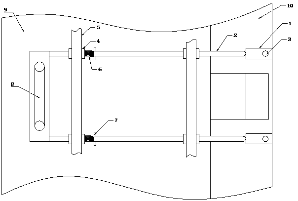
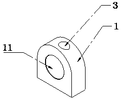
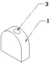
[0027] see Figure 1 to Figure 4 , which is a preferred embodiment of the present invention, this embodiment provides a locking device for vacuum equipment, the vacuum equipment includes a vacuum equipment body 10 and a door cover 9 rotatably arranged on the vacuum equipment body 10, the locking device is used for Lock the door cover 9 to a preset position away from the vacuum equipment body 10, and include:

[0028] The base 1 is arranged on the vacuum equipm...


PUM


Abstract

The invention discloses a locking device used for locking a door cover at the preset position away from a vacuum equipment body. The locking device comprises a base part arranged on the vacuum equipment body, and an inserting part arranged on the door cover. At least one concave part at least partially matched with the inserting part is arranged on the base part. The inserting part can move from an unlocking position to a locking position and from the locking position to the unlocking position on the concave parts. The invention further discloses the door cover which comprises the vacuum equipment body and is rotationally arranged on the vacuum equipment body, and the vacuum equipment of the locking device. The vacuum equipment body is connected with the door cover through a hinge structure. The locking device and the vacuum equipment are simple in structure and convenient to operate, and the vacuum environment of the vacuum equipment can be effectively guaranteed.

Description

technical field [0001] The invention relates to the technical field of locking devices, in particular to a locking device for vacuum equipment and vacuum equipment with the locking device. Background technique [0002] At present, the door cover and the base are often connected by locking methods such as door pin hinge and / or buckle connection during assembly. Due to the problems of dimensional accuracy, assembly accuracy and the elasticity of matching connectors such as sealing rings between the door cover and the base, the door pin hinged or buckle connection cannot make the door cover and the base fit tightly, and is not suitable for vacuum equipment middle. When some vacuum equipment uses door pin hinge and snap connection at the same time, its sealing effect can meet the requirements of use, but when opening or closing the door cover, it is necessary to turn the handle first to loosen the snap connection or to release the snap connection. The connection card is hooked...

Claims


Application Information

Patent Timeline
Patent Type & Authority Applications(China)
IPC IPC(8): F16B17/00
CPCF16B17/004
Inventor 张光海郑文岸李哲峰
Owner SHENZHEN YUANSU OPTOELECTRONICS TECH CO LTD
Learn More