plate tension rail

A technology of tensioning rail and printing plate, applied in the field of printing plate device, can solve the problems of inability to realize automatic operation and prolonging debugging time.

Active Publication Date: 2020-12-18
MAN ROLAND MASCHINEN AG
View PDF13 Cites 0 Cited by
  • Summary
  • Abstract
  • Description
  • Claims
  • Application Information

AI Technical Summary

Problems solved by technology

[0004] A disadvantage of the device shown in DE-OS 26 26 503 is that the plate clamping device has to be actuated by hand or with a tool, which leads to prolonged commissioning times
In addition, it is not possible to realize automatic manipulation

Method used


Image

  • plate tension rail
  • plate tension rail
  • plate tension rail

Examples


Embodiment Construction

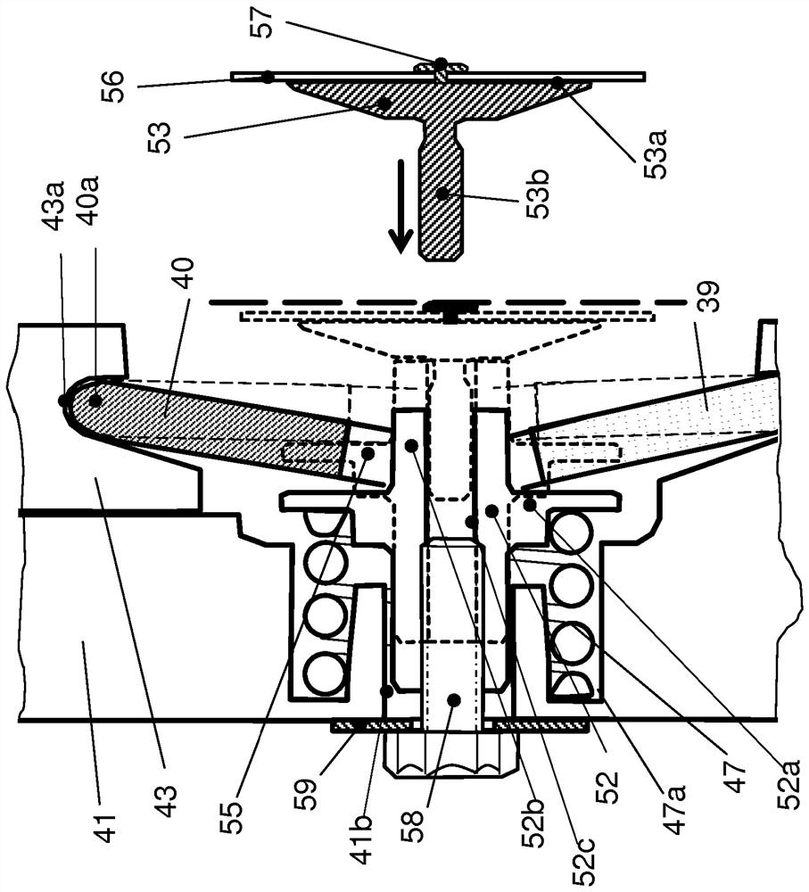
[0038] figure 1 A device according to the prior art is shown. The plate cylinder 1 is provided with a cylinder channel 2 for accommodating two plate tensioning rails 3 , only one of the two plate clamping rails being shown. The plate tensioning rail 3 is provided at the bottom 5 with a rail body 4 extending over the length of the plate cylinder 1 . The rail body 4 is displaceable in the drum channel 2 in the direction of the left and right lateral delimitations 6 , 7 . A plurality of fulcrums 8 for pivotably accommodating the respective lower end 11 of the lower rail link 9 of the toggle mechanism is arranged in an axis-parallel direction, the lower rail link of the toggle mechanism The upper end 12 of the upper track link 10 is then hingedly connected to the lower end 13 of the upper track link 10 , wherein the upper end 14 of the upper track link 10 is pivotably supported in a fulcrum 15 . The fulcrum 15 is arranged on an upper rail 16 which is pivotable relative to the r...


PUM


Abstract

The invention relates to a device for clamping flexible pressure plates by means of lifting elements (39, 40) which are in the form of a knee lifting drive and arranged in a manner parallel to an axis on a lower rail (43). In order to improve the clamping effect, the lower rail (43) is mounted so that it can be moved linearly and radially with respect to the plate cylinder (1) and with respect to an upper rail (44). One or more spring elements (47) acting upon the lifting elements (39, 40) are provided for moving the lower rail into a clamping position by displacing the lifting element (39, 40) into a working position. One or more expandable pneumatic or hydraulic elements (50) for moving the lower rail (43) into an open position by moving the lifting elements (39, 40) from the working position are provided.

Description

technical field [0001] The invention relates to a device for clamping a flexible printing form on a printing form cylinder of a web printing press according to the preamble of claim 1 . Background technique [0002] A printing plate clamping device is known from DE-OS 26 26 503, in which the printing plate end is clamped on parallel clamping surfaces and vertical Between the clamping plates guided here. The movement of the clamping plates takes place via toggle mechanisms with axes arranged in parallel, on which the eccentrics act in each case in the area of ​​the toggle joints [0003] superior. The eccentrics are arranged on a common shaft and are jointly actuated when the shaft turns. The movement of the toggle mechanism is accomplished by moving beyond the extended position into a stable top dead center position against a stop configured as a second eccentric. In order to bring the toggle joint out of its stable top dead center position, the second eccentric is pivot...

Claims


Application Information

Patent Timeline
Patent Type & Authority Patents(China)
IPC IPC(8): B41F27/12
CPCB41F27/12B41F27/1262
Inventor H-G.艾特尔M.罗特尔
Owner MAN ROLAND MASCHINEN AG
Why Eureka
Try Eureka