
wheel suspension

A wheel suspension and wheel technology, applied in the direction of suspension, elastic suspension, vehicle components, etc., to achieve the effect of high driving comfort

Active Publication Date: 2021-04-20
ZF FRIEDRICHSHAFEN AG
View PDF11 Cites 0 Cited by
  • Summary
  • Abstract
  • Description
  • Claims
  • Application Information

AI Technical Summary

Problems solved by technology

A more detailed design of the bearing shown only through the bore is not available from this document

Method used


Image

  • wheel suspension
  • wheel suspension
  • wheel suspension

Examples


Embodiment Construction

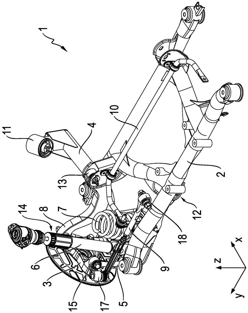
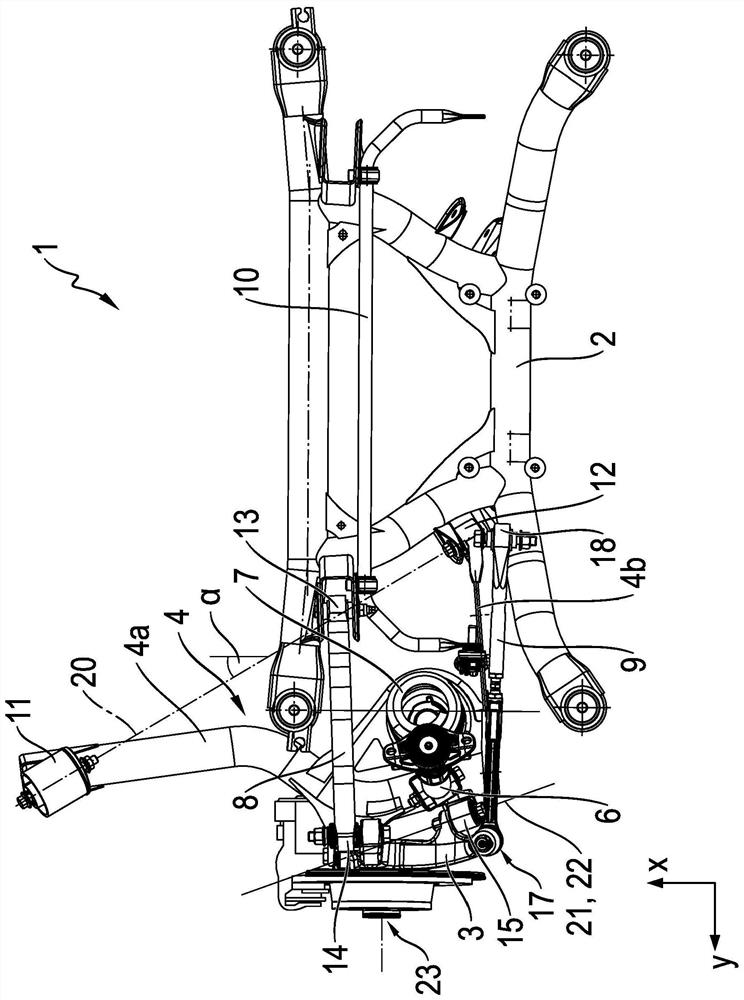
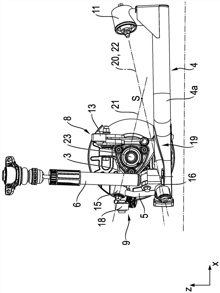
[0030] exist Figure 1 to Figure 4 A wheel suspension 1 for a motor vehicle according to a single exemplary embodiment of the invention is shown in different aspects and explained below. Since the four figures relate to a single exemplary embodiment of the invention, the same reference numerals are used to designate the same components in the figures, so that the explanations made for the reference numerals or corresponding components apply equally to all figures, and accordingly Figures are not repeated for each figure. In all figures, the directions are defined by the specification of a coordinate system, x corresponding to the vehicle longitudinal direction, y corresponding to the vehicle transverse direction and z corresponding to the vehicle height direction.

[0031] figure 1 Shown is a wheel suspension 1 attached to an axle carrier 2 for a motor vehicle, wherein, for reasons of clarity, only the wheel suspension with respect to the (not shown) left side of the motor ...


PUM


Abstract

A wheel suspension (1) for a motor vehicle, with a wheel carrier (3), which is mounted so as to be pivotable relative to a control rod (4) guiding the wheel, wherein the control rod (4) guides the wheel Comprising a longitudinal tie rod region (4a) with a vehicle body-side front bearing (11) and a transverse tie rod region (4b) with a vehicle body-side rear bearing (12), characterized in that the vehicle body-side rear bearing (12) The axis of rotation ( 20 ) extending through the body-side bearings ( 11 , 12 ) parallel to the wheel-guiding tie rod ( 4 ) is oriented axially.

Description

technical field [0001] The invention relates to a wheel suspension for a motor vehicle according to the preamble of claim 1 and to a tie rod guiding a wheel according to the preamble of claim 17 . Background technique [0002] A wheel suspension for a motor vehicle according to the features of the preamble of claim 1 is known from the prior art. In this regard, reference should be made to DE 10 2013 211 535 A1, which discloses a steerable rear wheel suspension for a motor vehicle. The wheel suspension described therein comprises, in particular, a wheel-guiding tie rod, which has a longitudinal tie rod region and a transverse tie rod region, wherein the longitudinal tie rod region is provided with a front bearing on the vehicle body side, and the transverse tie rod region is provided with a front bearing on the vehicle body side. The bearings are further inward than the rear bearings on the body side. The essentially L-shaped wheel-guiding tie rod formed in this way is pivo...

Claims


Application Information

Patent Timeline
Patent Type & Authority Patents(China)
IPC IPC(8): B60G3/28B60G7/00B60G7/02
CPCB60G3/28B60G7/001B60G7/008B60G7/02B60G2200/144B60G2200/154B60G2200/184B60G2204/1431B60G2204/41B60G2204/422B60G2206/121B60G2206/122B60G2206/15B60G2400/05142B60G2400/05144B60G2204/418B60G3/202B60G2204/148B62D7/20
Inventor C·哈克S·U·西德迪奎E·芬克拜纳M·默勒
Owner ZF FRIEDRICHSHAFEN AG
Learn More