Punching mold convenient to disassemble and replace punching head

A technology of stamping dies and stamping heads, which is applied in the direction of forming tools, manufacturing tools, metal processing equipment, etc., can solve the problems of inconvenient installation and disassembly of stamping heads, and reduce work efficiency, so as to achieve simple and fast installation and disassembly, improve work efficiency, and facilitate replacement Effect

Inactive Publication Date: 2018-08-24
王玲芳
View PDF0 Cites 13 Cited by
  • Summary
  • Abstract
  • Description
  • Claims
  • Application Information

AI Technical Summary

Problems solved by technology

[0003] The purpose of the present invention is to solve the disadvantages of inconvenient installation and disassembly of the stamping head in the prior art, and reduce the work efficiency, and propose a stamping die that is easy to disassemble and replace the stamping head

Method used


Image

  • Punching mold convenient to disassemble and replace punching head
  • Punching mold convenient to disassemble and replace punching head

Examples


Embodiment Construction

[0014] The following will clearly and completely describe the technical solutions in the embodiments of the present invention with reference to the accompanying drawings in the embodiments of the present invention. Obviously, the described embodiments are only some, not all, embodiments of the present invention.

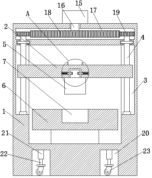
[0015] refer to Figure 1-2 , a stamping die that is easy to disassemble and replace the stamping head, including a housing 1, the housing 1 is hollow, and the housing 1 is provided with a mounting groove 20 with an opening downward, and the upper inner wall of the mounting groove 20 is fixedly connected with a cylinder 21 , and the output end of the cylinder 21 is connected with a piston rod 22, and the end of the piston rod 22 away from the cylinder 21 is connected with a universal wheel 23. When the mobile device is needed, the cylinder 21 drives the universal wheel 23 at one end of the piston rod 22 to move out of the installation groove 20 until the housing 1 is...


PUM


Abstract

The invention discloses a punching mold convenient to disassemble and replace a punching head. The punching mold comprises a shell; the shell is hollowed; a feed port communicating with the internal of the shell is formed in the front side wall of the shell; an opening of the feed port is rotationally connected with a cover plate; a mounting plate, transversely arranged, is slidingly connected into the shell; chutes, matched with the mounting plate, are symmetrically formed in the inner walls of two sides of the shell; thread rods, vertically arranged, are rotationally connected into the chutes; the thread rods penetrate through the mounting plate, and are in threaded connection with the mounting plate; a driving device matched with the thread rods is arranged at the upper end of the shell; the punching head is arranged on the lower side wall of the mounting plate; a worktable is fixedly connected to the inner wall of the lower side of the shell; and an object placing tank matched withthe punching head is arranged on the upper side wall of the worktable. The punching mold is simple in operation, convenient to use, simple and fast in installation and disassembly of the punching head and convenient to replace the damaged punching head, and improves the working efficiency.

Description

technical field [0001] The invention relates to the technical field of dies, in particular to a stamping die which is convenient for disassembling and replacing a stamping head. Background technique [0002] Mold, various molds and tools used in industrial production for injection molding, blow molding, extrusion, die-casting or forging forming, smelting, stamping and other methods to obtain the required products. In the stamping tool, the stamping head used to stamp the workpiece will be worn after long-term use and needs to be replaced, but the installation and disassembly of the stamping head is inconvenient, which reduces the work efficiency; therefore, we propose a It is convenient to disassemble and replace the stamping die of the stamping head to solve these problems. Contents of the invention [0003] The purpose of the present invention is to solve the disadvantages of inconvenient installation and disassembly of the stamping head in the prior art, and reduce the...

Claims


Application Information

Patent Timeline
Patent Type & Authority Applications(China)
IPC IPC(8): B21D37/10B21D37/04
CPCB21D37/10B21D37/04
Inventor 王玲芳
Owner 王玲芳
Why Eureka
Try Eureka