Supercharge Your Innovation With Domain-Expert AI Agents!

Manipulator for die-casting machine

A technology of manipulators and die-casting machines, applied in manipulators, program-controlled manipulators, manufacturing tools, etc., can solve problems such as inconvenient picking of manipulators

Inactive Publication Date: 2018-08-24
太仓鸿鑫精密压铸有限公司
View PDF3 Cites 0 Cited by
  • Summary
  • Abstract
  • Description
  • Claims
  • Application Information

AI Technical Summary

Problems solved by technology

[0002] After the die-casting is completed, the alloy needs to be taken out of the mold by a robot, which is inconvenient to take out by the existing robot

Method used


Image

  • Manipulator for die-casting machine

Examples


Embodiment Construction

[0009] The specific implementation manners of the present invention will be further described below in conjunction with the drawings and examples. The following examples are only used to illustrate the technical solution of the present invention more clearly, but not to limit the protection scope of the present invention.

[0010] The technical scheme of concrete implementation of the present invention is:

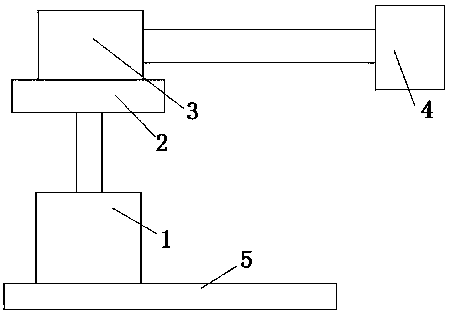
[0011] Such as figure 1 as shown,

[0012] A manipulator for a die-casting machine, characterized in that it includes a base 5, a servo motor 1 and a telescopic cylinder 3; A rotating disk 2 is fixed on the motor shaft, and the rotating disk 2 is perpendicular to the motor shaft of the servo motor 1. The telescopic cylinder 3 is installed on the rotating disk 2, and the telescopic rod of the telescopic cylinder 3 is placed flat. hand 4.

[0013] The working principle of the present invention is: the servo motor 1 drives the rotating shaft to rotate, the product rotates...


PUM


Abstract

The invention discloses a manipulator for a die-casting machine. The manipulator comprises a base, a servo motor and a telescopic cylinder. The base is horizontally arranged. The servo motor is mounted on the base. A motor shaft of the servo motor is vertically arranged. A rotary disk is fixed to the motor shaft of the servo motor. The rotary disk is perpendicular to the motor shaft of the servo motor. The telescopic cylinder is mounted on the rotary disk. A telescopic rod of the telescopic cylinder is arranged horizontally. A gripper is arranged on the telescopic rod of the telescopic cylinder. The manipulator has the beneficial effect that the manipulator can transfer an alloy subjected to die-casting from one place to another place.

Description

technical field [0001] The invention relates to the technical field of die casting, in particular to a manipulator for a die casting machine. Background technique [0002] After the die-casting is completed, the alloy needs to be taken out of the mold by a manipulator, which is inconvenient for the existing manipulator to take materials. Contents of the invention [0003] The object of the present invention is to provide a die-casting machine manipulator, which can transfer the die-cast alloy from one place to another. [0004] To achieve the above object, the present invention provides the following technical solutions: [0005] A manipulator for a die-casting machine is characterized in that it includes a base, a servo motor and a telescopic cylinder; the base is placed flat, the servo motor is installed on the base, the motor shaft of the servo motor is vertically placed, and a rotating disk is fixed on the motor shaft of the servo motor. The rotating disk is perpendi...

Claims


Application Information

Patent Timeline
Patent Type & Authority Applications(China)
IPC IPC(8): B25J9/04
CPCB25J9/042
Inventor 钱伟国
Owner 太仓鸿鑫精密压铸有限公司
Features
  • R&D
  • Intellectual Property
  • Life Sciences
  • Materials
  • Tech Scout
  • Unparalleled Data Quality
  • Higher Quality Content
  • 60% Fewer Hallucinations
Learn More