Body frame structure

a frame and body technology, applied in the field of body frame structure, can solve the problems of increasing the thickness the rigidity of the whole frame, and the difficulty of increasing the productivity under mass production, so as to suppress the vibration of the steering gear box, suppress the increase in weight, and lighten the weight

Inactive Publication Date: 2009-04-21
HONDA MOTOR CO LTD
View PDF34 Cites 50 Cited by
  • Summary
  • Abstract
  • Description
  • Claims
  • Application Information

AI Technical Summary

Benefits of technology

[0016]A problem that the invention is to solve is that by solving the problem that the rigidity is high over the entirety of the frame, the invention provides a body frame structure which can increase the load transmission performance and the shape maintaining performance, and provides a body frame structure which can suppress the increase in vehicle weight by solving the problem that requires the increase in thickness so as to increase the rigidity of the frame.
[0017]In addition, another problem that the invention is to solve is that by solving the problem that the rigidity of the frame is low, the invention provides a body frame structure which can not only increase the rigidity of the frame but also realize the suppression of increase in vehicle weight.
[0018]Furthermore, a further problem that the invention is to solve is that by solving the problem that the rigidity of the frame is low, the invention provides a body frame structure which can not only realize the suppression of increase in vehicle weight while increasing the frame rigidity but also increase the accuracy at the locations where dimensional accuracy is required by solving the problem that the assembling errors are produced.

Problems solved by technology

In the body frame structure 300 shown in FIG. 20, however, since the subframe 301 is such as to be formed integrally by die casting the aluminum alloy, the rigidity of the whole frame is high, and for example, in order to increase the load transmission performance which disperses and absorbs an excessive load such as an impact which is applied to the subframe 301, when such a thing occurs, and the shape maintaining performance which maintains an initial shape of the subframe 301, the shape of the subframe 301 needs to be complex, and this leads to a problem that such a complex shape makes it difficult to increase the productivity under mass production.
In addition, in the body frame structure 310 shown in FIG. 21, since the subframe 311 is made up of the aluminum alloy extruded product, the rigidity of the whole frame is low, and in order to increase the rigidity at, for example, a fixing portion of such as a steering gear box (not shown) where a large steering reaction is generated, a fixing portion such as a fixing portion of a suspension where there is a large input and a connecting portion to the body where road surface vibrations are inputted, the thickness of those portions needs to be increased, leading to a drawback that the increase in thickness calls for an increase in vehicle weight.
In addition, in the body frame structure 310, since the subframe (the front subframe) is divided into the front frame portion 312 and the rear frame portion 316, the left and right frame portions 314, 314, the left and right front corner portions 313, 313 and the left and right rear corner portions 315, 315, there occur assembling errors when these members are assembled, leading to a problem that the body frame structure 310 is not suitable for locations where dimensional accuracy is required.

Method used


Image

  • Body frame structure
  • Body frame structure
  • Body frame structure

Examples


Embodiment Construction

[0084]A best mode for carrying out the invention will be described based on the accompanying drawings. Note that front / forward, rear / rearward, left / leftward, right / rightward, up / upward and down / downward denote such directions as viewed from the driver, Fr, Rr, L and R denote front side, rear side, left side and right side, respectively, and CL denotes the center of a vehicle (a transverse center of a vehicle).

[0085]Firstly, a vehicle will be described briefly based on FIGS. 1 to 3.

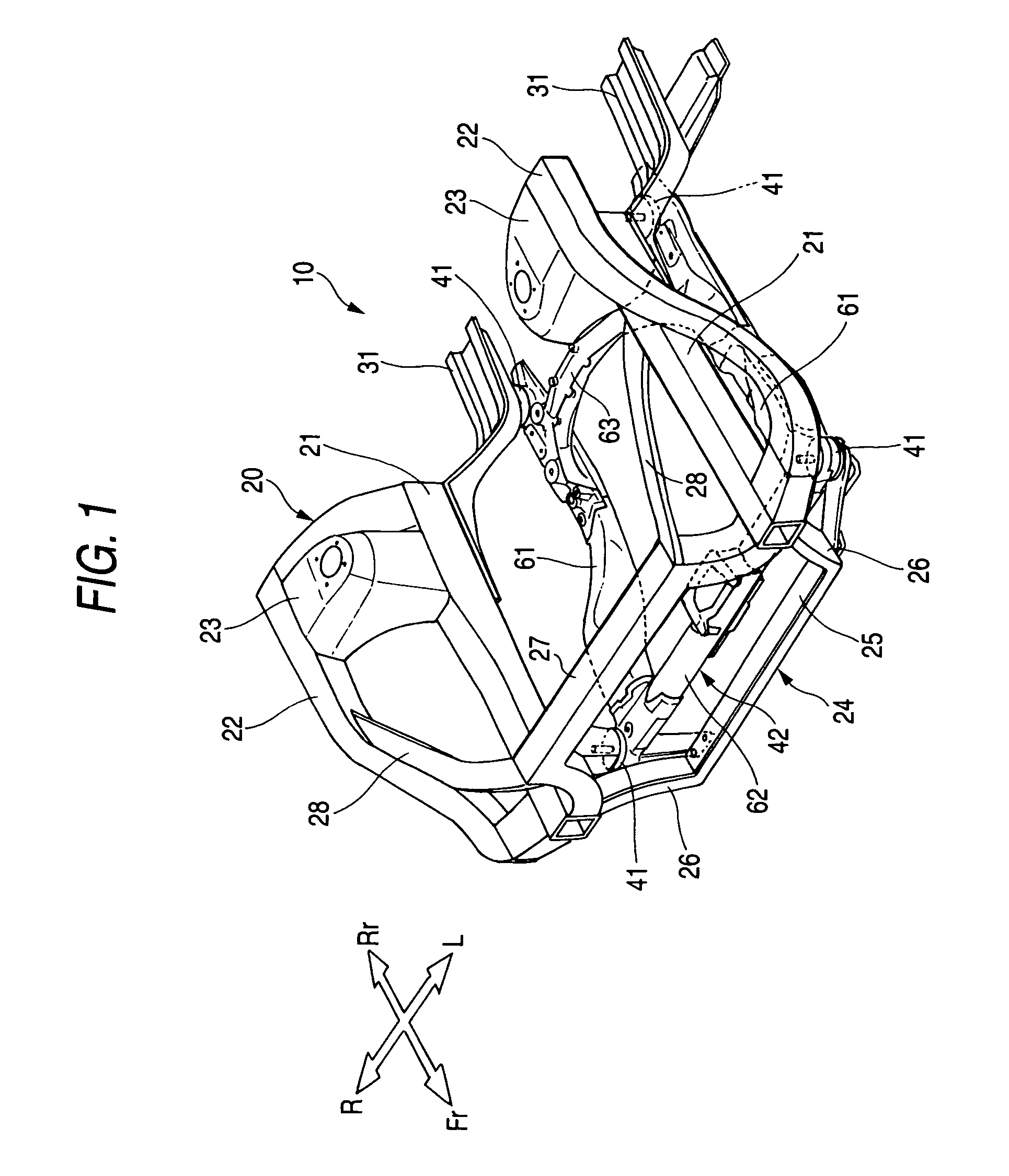
[0086]FIG. 1 is a perspective view of a front part of a vehicle according to the invention. A body frame (a body) 20 of a vehicle 10 is an integral or monocoque body in which a front part construction thereof is made up mainly of left and right front side frames 21, 21 which extend longitudinally on both sides of a front part of the body, left and right upper frames 22, 22 which extend longitudinally on transversely outboard sides of and above the front side frames 21, 21, left and right front damper housi...


PUM


Abstract

A front subframe 42 is formed of an aluminum alloy into a frame that is formed substantially into a shape of parallel crosses or into a rectangular shape and is made up of left and right front joint portions 64, 64 and left and right rear joint portions 71, 71 which are disposed at corners of the frame that is formed substantially into the shape of parallel crosses or the rectangular shape, and left and right longitudinal members 61, 61, and front and rear cross members 62, 67 which connect the joint portions 64, 64, 71, 71 together. The left and right front joint portions 64, 64 and the left and right rear joint portions 71, 71 are formed of an aluminum alloy die-cast product, whereas the left and right longitudinal members 61, 61 are formed of an aluminum alloy wrought product. In addition, connecting locations 76 . . . of a camber angle adjusting mechanism 157 are formed of an aluminum alloy die-cast product. Additionally, a rear cross member compound 63 is formed of an aluminum alloy die-cast product.

Description

CROSS-REFERENCE TO RELATED APPLICATION[0001]This application is a National Stage entry of International Application No. PCT / JP2005 / 006562, filed Mar. 29, 2005, the entire specification claims and drawings of which are incorporated herewith by reference.TECHNICAL FIELD[0002]The present invention relates to a body frame structure having a front subframe on which drive train parts, steering system parts or suspension system parts are installed and which is attached to a body side.BACKGROUND ART[0003]As body frame structures, those are now in practical use which have a subframe which supports drive train parts including a power source, steering system parts such as a steering gear box and suspension system parts such as suspensions, and camber and caster angles adjusting mechanisms.[0004]In those body frame structures which are now in practical use, it has been practically sufficient that a front subframe is formed substantially in parallel crosses or into a rectangle in such a manner t...

Claims


Application Information

Patent Timeline
Patent Type & Authority Patents(United States)
IPC IPC(8): B62D21/11B60G3/20B60G7/00B62D21/00B62D25/08B62D25/20
CPCB60G3/20B62D21/11B62D25/082B60G2200/144B60G2204/143B60G2204/15
Inventor OGAWA, TSUTOMUKIMURA, KUNIHIKOFUKUCHI, FUMIAKIONO, SHUICHIOTAKE, SHUJIOKU, YASUNORIKOGA, HIDEKI
Owner HONDA MOTOR CO LTD
Why Eureka
Try Eureka