Recessed LED Downlight

a led downlight and recessed technology, applied in the direction of fixed installation, lighting and heating equipment, lighting support devices, etc., can solve the problems of not providing an integral mounting configuration, unable to provide a removable led pc board, and led downlights that are plagued by many problems

Active Publication Date: 2010-11-25
ABL IP HLDG
View PDF24 Cites 53 Cited by
  • Summary
  • Abstract
  • Description
  • Claims
  • Application Information

AI Technical Summary

Benefits of technology

[0006]In an alternative implementation of the present invention, a downlight assembly includes a downlight can, a unitary die-cast cap, a LED array, a reflector and lens assembly, and a finishing trim. The downlight can has a tubular can wall. The unitary die-cast cap is mounted inside the downlight can and includes a base section, a plurality of heat-sink fins, and an interior plate. The base section has an exterior base-surface forming an exterior top-surface of the downlight can and an exterior-wall for direct contact attachment to the tubular can wall. The plurality of heat-sink fins extend from the base sectio...

Problems solved by technology

However, current LED-based lighting fixtures, such as LED downlights, are plagued by many problems.
One problem associated with some current LED downlights is that they lack a heat sink that is integral with the can housing such that the entire LED downlight assembly becomes a heat sink for dissipating heat away from the LEDs.
Another problem asso...

Method used


Image

  • Recessed LED Downlight
  • Recessed LED Downlight
  • Recessed LED Downlight

Examples


Embodiment Construction

[0018]Although the invention will be described in connection with certain preferred embodiments, it will be understood that the invention is not limited to those particular embodiments. On the contrary, the invention is intended to include all alternatives, modifications and equivalent arrangements as may be included within the spirit and scope of the invention as defined by the appended claims.

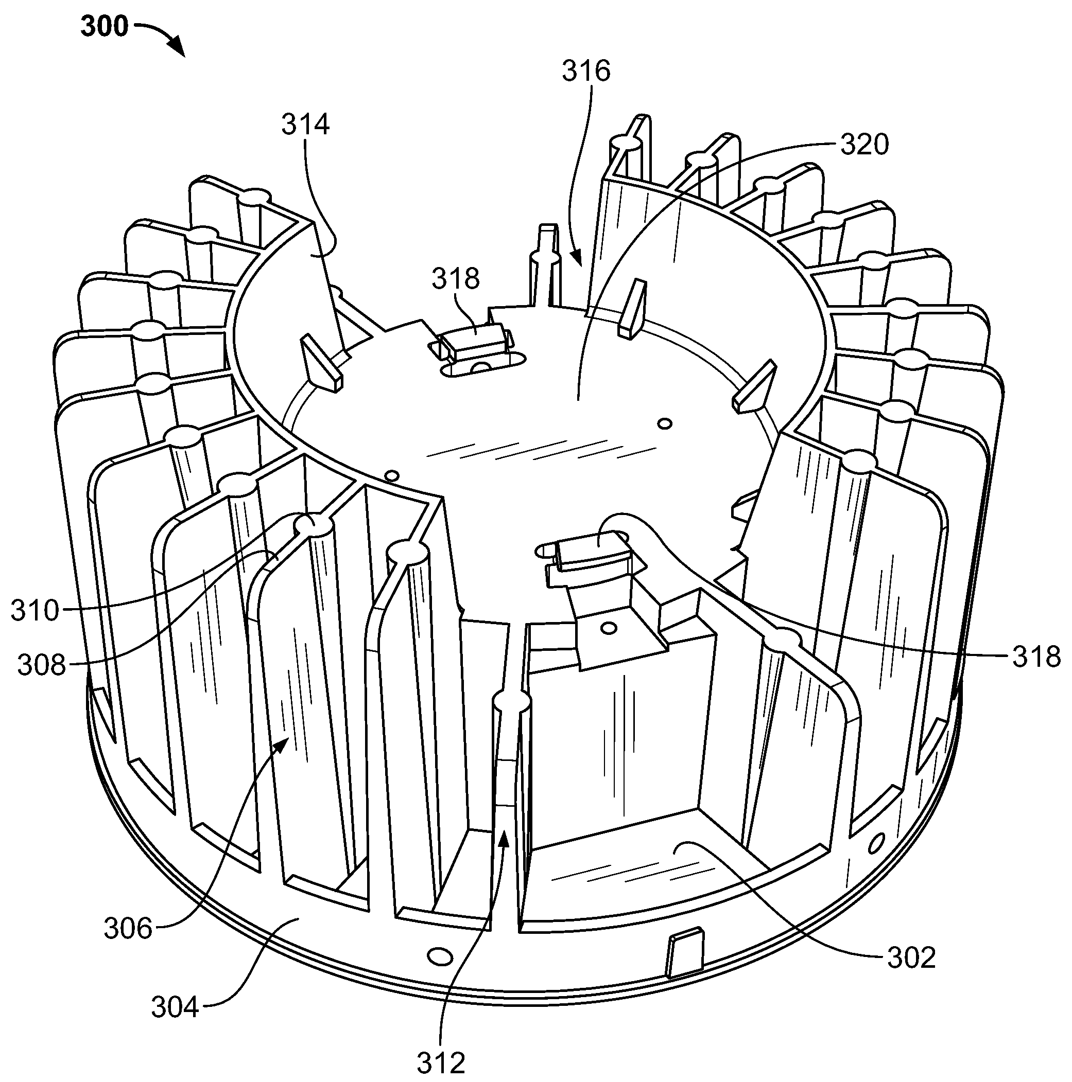
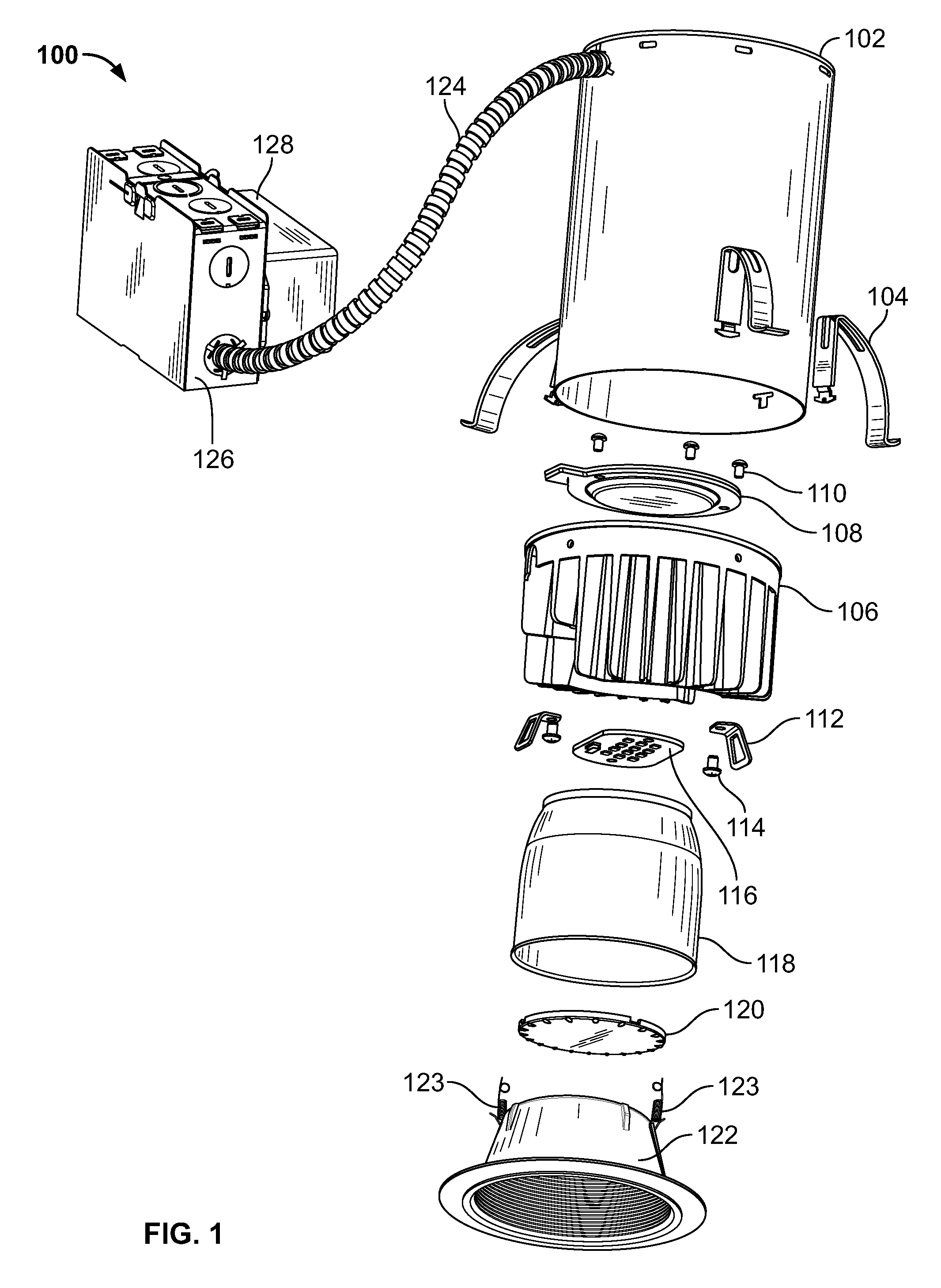
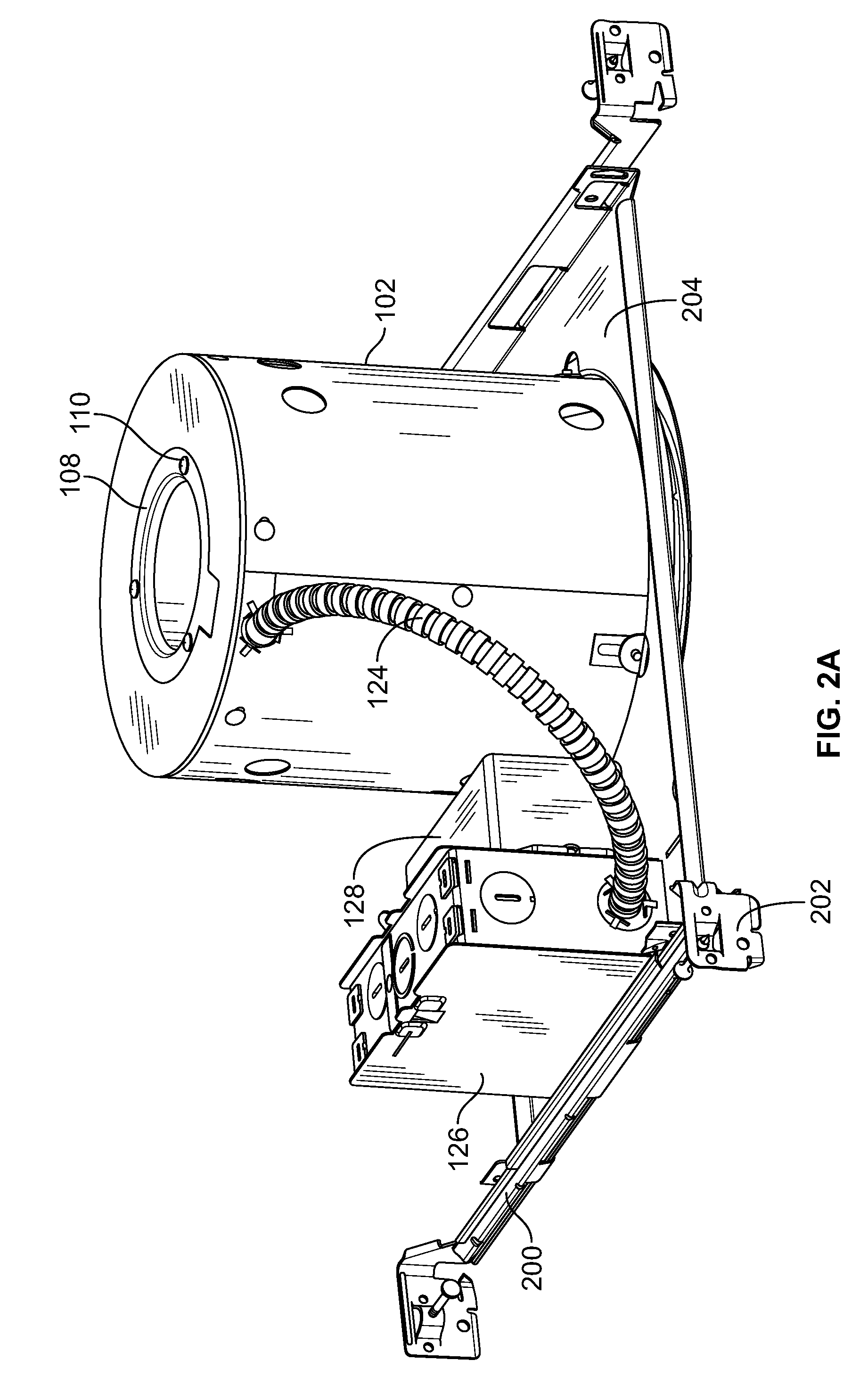
[0019]Referring to FIG. 1, a downlight fixture assembly 100 for a recessed light includes a downlight can 102 having three support members 104 positioned generally symmetrically on an exterior surface of the downlight can 102. The can 102 is an open-ended hollow tubular wall (shown in cylindrical form), similar to standard downlight cans, having an exterior wall-surface and an interior wall-surface. A unitary die-cast cap 106, which is designed to fit inside the downlight can 102, includes a removable cutout plate 108 mounted generally flush with an exterior base-surface of the cap 106 via a ...


PUM


Abstract

A unitary die-cast cap for a downlight can includes a base section and a plurality of heat-sink fins. The base section is a plate that includes an interior base-surface, an exterior base-surface, and an exterior wall-surface. The exterior base-surface, which is an opposite surface of the interior base-surface, forms an exterior top-surface of a downlight tubular can. The exterior wall-surface is configured to be positioned in direct attachment to an interior wall-surface of the downlight can. The plurality of heat-sink fins extend from the interior base-surface and form a substantially cylindrical exterior heat-sink wall touching or in close proximity to the interior wall-surface of the downlight can.

Description

FIELD OF THE INVENTION[0001]This invention is directed generally to recessed lighting systems, and, more particularly, to a unitary die-cast cap for a recessed LED downlight.BACKGROUND OF THE INVENTION[0002]In comparison to other types of light fixtures, e.g., incandescent and fluorescent light fixtures, light-emitting diodes (“LEDs”) provide numerous advantages. For example, LED-based lighting fixtures (i) dramatically reduce energy consumption based on relatively low wattage, (ii) have a relatively longer life (e.g., 50,000 hours vs. 2,000-5,000 hours for incandescent light fixtures), (iii) provide cool operation (e.g., reduce energy costs by reducing air conditioning loads), (iv) contain no lead or mercury (e.g., eliminate special recycling requirements), and (v) do not have ultraviolet emissions.[0003]However, current LED-based lighting fixtures, such as LED downlights, are plagued by many problems. One problem associated with some current LED downlights is that they lack a heat...

Claims


Application Information

Patent Timeline
IPC IPC(8): F21S8/00F21V29/00F21V29/15
CPCF21S8/026F21V21/03F21V21/04F21V29/773F21Y2101/02F21V29/75F21V29/004F21V21/048F21Y2115/10
Inventor ROOS, SCOTTLAYNE, BRUCEWNEK, MATT
Owner ABL IP HLDG
Why Eureka
Try Eureka