Pure electric bus

A bus, pure electric technology, applied in electric vehicle charging technology, electric power device, vehicle maintenance and other directions, can solve the problems of cumbersome replacement, parking at the charging station to charge, etc., to achieve quick use, accurate positioning, and save waiting time Effect

Inactive Publication Date: 2018-08-24
叶桂阳
View PDF0 Cites 2 Cited by
  • Summary
  • Abstract
  • Description
  • Claims
  • Application Information

AI Technical Summary

Problems solved by technology

However, the stored electric energy of the battery on the electric bus is limited. When the electric energy of the battery on the electric bus is exhausted, the electric bus can only be charged at the charging station, and the battery of a general electric bus is installed in the lower part of the car body. It is also more cumbersome to replace the battery to supplement the electric energy

Method used


Image

  • Pure electric bus
  • Pure electric bus
  • Pure electric bus

Examples


Embodiment 1

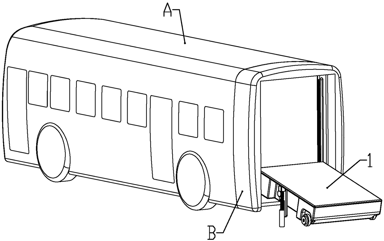
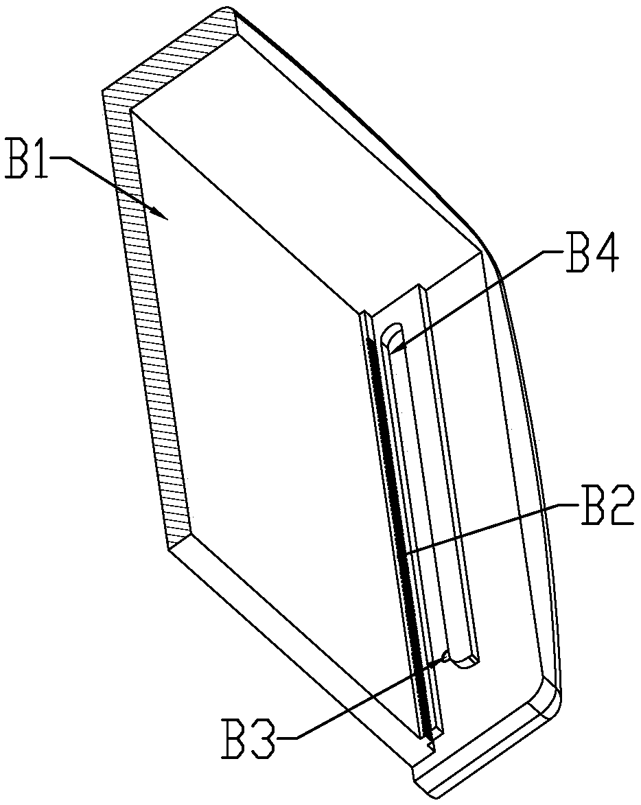
[0059] according to Figure 1 to Figure 11 As shown, a pure electric bus described in this embodiment includes a car body A, a battery assembly mounting seat B fixedly installed at the rear end of the car body, and a battery assembly movably mounted in the battery assembly mounting seat 1.

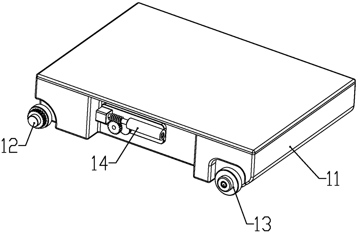
[0060] The battery assembly includes a rectangular frame 11, a front axle 12 installed at the front end of the frame, two rear axles 13 installed at the rear of the frame, and two symmetrically mounted on both sides of the frame. Rotate lift assembly 14.

[0061] The front wheel shaft is rotatably connected to the lower part of the frame body; the two ends of the front wheel shaft located outside the frame body are respectively fixedly connected with a front wheel 121, a second gear 122 and a limit guide post 123 from the inside to the outside; The front wheel, the second gear and the limiting guide post are arranged coaxially and their outer diameters are successively reduced; the dista...

Embodiment 2

[0087] combine Figures 12 to 19 As shown, this embodiment makes the following improvements on the basis of embodiment 1: a cooling assembly is installed in the battery assembly, and the cooling assembly includes a heat collecting pipe installed in the frame for absorbing the heat emitted by the battery , the radiator installed in the frame, and the cooling pump used to drive the cooling liquid to circulate between the heat collection pipeline and the radiator.

[0088] The radiator includes a heat dissipation plate 82, a heat dissipation seat 83 and a water wheel seat 84 which are sealed and connected in sequence; a heat dissipation channel 831 is opened on the end surface of the heat dissipation seat facing the heat dissipation plate, and the heat dissipation channel is arranged in a circuitous manner as shown in the figure. In the shape of a serpentine tube, the side of the cooling seat is connected with a liquid inlet joint a832 and a liquid outlet joint a833, and the liqu...


PUM


Abstract

The invention belongs to the technical field of electric automobiles and discloses a pure electric bus. The pure electric bus comprises an automobile body, a battery component installation seat fixedly installed at the rear end of the automobile body and a battery component movably installed in the battery component installation seat; the battery component comprises a rectangular frame, a front axle installed at the front end of the frame, two rear axles installed on the rear portion of the frame and two rotary lifting components symmetrically installed on the two sides of the frame; and eachrear wheel drive component located on one side of the corresponding rear axle is installed in the frame. When the electric quantity of the electric bus is insufficient, the battery component is directly replaced, the charging waiting time is saved, and therefore the electric bus can be put into use quickly; and through forward and reverse rotation of stepping motors, rotation of rear wheels and telescopic motion of locating rods can be switched.

Description

technical field [0001] The invention belongs to the technical field of electric vehicles, in particular to a pure electric bus. Background technique [0002] With the rapid development of electric vehicles and the increase of national investment, electric buses have also developed accordingly. The national industrial policy also encourages the development of electric buses in the direction of industrialization. However, the stored electric energy of the battery on the electric bus is limited. When the electric energy of the battery on the electric bus is exhausted, the electric bus can only be charged at the charging station, and the battery of a general electric bus is installed in the lower part of the car body. It is also more complicated to replace the battery to supplement the electric energy. Contents of the invention [0003] The technical problem to be solved by the present invention is to provide a pure electric bus in view of the deficiencies in the prior art. ...

Claims


Application Information

Patent Timeline
IPC IPC(8): B60K1/04B60S5/06
CPCB60K1/04B60K2001/0416B60S5/06Y02T90/12
Inventor 叶桂阳
Owner 叶桂阳
Why Eureka
Try Eureka