
Engine heat dissipation system, vehicle and engine heat dissipation method

A technology of a heat dissipation system and a heat dissipation method, which is applied in the layout of the cooling combination of radiators, vehicle components, and power units, can solve the problems that the normal operation of the engine cannot be guaranteed, and the heat dissipation requirements of high-power engines cannot be met.

Active Publication Date: 2018-08-24
BEIJING AUTOMOTIVE IND CORP +1
View PDF8 Cites 8 Cited by
  • Summary
  • Abstract
  • Description
  • Claims
  • Application Information

AI Technical Summary

Problems solved by technology

In related technologies, most of the radiators are arranged at the position of the air intake grille in front of the vehicle, and at the same time, a fan with a large air intake volume is installed to increase the air intake area to dissipate heat from the engine. However, the above methods cannot meet the heat dissipation requirements of high-power engines. , especially in extreme conditions, the normal operation of the engine cannot be guaranteed

Method used


Image

  • Engine heat dissipation system, vehicle and engine heat dissipation method
  • Engine heat dissipation system, vehicle and engine heat dissipation method
  • Engine heat dissipation system, vehicle and engine heat dissipation method

Examples


Embodiment Construction

[0027] Specific embodiments of the present disclosure will be described in detail below in conjunction with the accompanying drawings. It should be understood that the specific embodiments described here are only used to illustrate and explain the present disclosure, and are not intended to limit the present disclosure.

[0028] In this disclosure, unless stated otherwise, the used orientation words such as "upper" and "lower" usually refer to the definition based on the drawings of the corresponding drawings, and "front" and "rear" refer to Relative to the normal driving direction of the vehicle, "inside" and "outside" refer to the inside and outside of the outline of the corresponding part. In addition, the terms "first", "second", and the like used in the present disclosure are for distinguishing one element from another, and do not have sequence or importance. In addition, when the following description refers to the accompanying drawings, the same numerals in different d...


PUM


Abstract

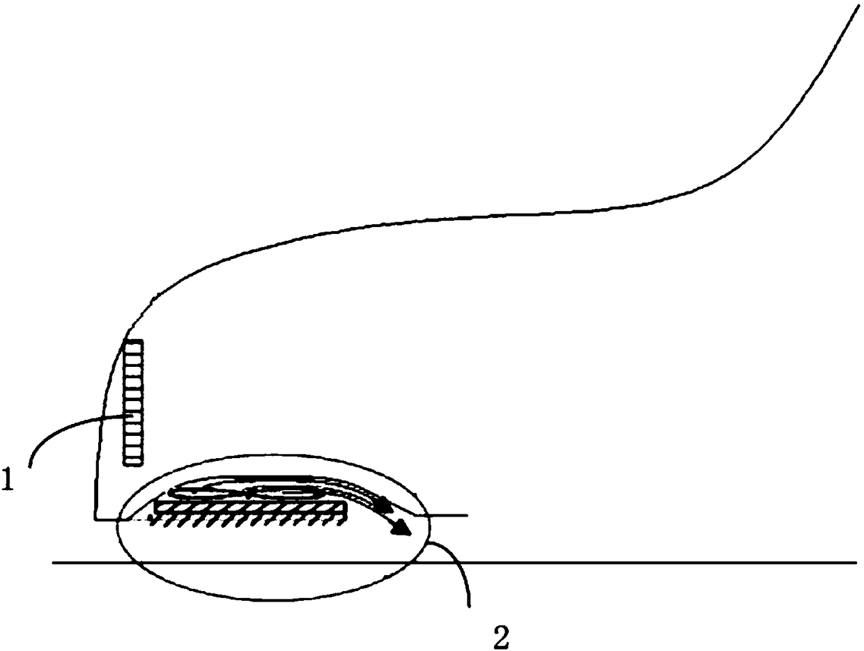
The invention relates to an engine heat dissipation system, a vehicle and an engine heat dissipation method. The engine heat dissipation system comprises a main heat dissipation device arranged in front of the vehicle and an auxiliary heat dissipation device connected with the main heat dissipation device and arranged at the bottom of the vehicle. The auxiliary heat dissipation device comprises anauxiliary heat dissipater fixed to the bottom of the vehicle, an air-inlet grille used for sealing the auxiliary heat dissipation device and a first controller used for controlling the air-inlet grille to open or close. The main heat dissipation device and the auxiliary heat dissipation device are matched, and especially under the limiting condition that the main heat dissipation device cannot meet the heat dissipation requirement of an engine, the auxiliary heat dissipation device can conduct supplementary heat dissipation; due to the fact that the auxiliary heat dissipation device is arranged at the bottom of the vehicle, flowing air in the traveling process of the vehicle is fully used for dissipating heat, and the first controller controls the air-inlet grille to open or close so as to meet the heat dissipation requirements of the engine under different working conditions; and the auxiliary heat dissipation device is arranged at the bottom of the vehicle, so that the arrangement space at the bottom of the vehicle is fully used, and the structure is more compact.

Description

technical field [0001] The present disclosure relates to the field of engine heat dissipation, and in particular, relates to an engine heat dissipation system, a vehicle, and an engine heat dissipation method. Background technique [0002] Engine heat dissipation, especially the heat dissipation of fuel cell vehicle engines, is one of the difficulties in vehicle development. In related technologies, most of the radiators are arranged at the position of the air intake grille in front of the vehicle, and at the same time, a fan with a large air intake volume is installed to increase the air intake area to dissipate heat from the engine. However, the above methods cannot meet the heat dissipation requirements of high-power engines. , especially in extreme conditions, the normal operation of the engine cannot be guaranteed. Contents of the invention [0003] The first object of the present disclosure is to provide an engine heat dissipation system, which can meet the heat dis...

Claims


Application Information

Patent Timeline
Patent Type & Authority Applications(China)
IPC IPC(8): B60K11/06B60R19/52
CPCB60K11/06B60R19/52Y02T10/88
Inventor 李学明
Owner BEIJING AUTOMOTIVE IND CORP
Learn More