Self-positioning plastic vacuum tank

A vacuum tank and self-positioning technology, which is applied to the layout of reservoirs, brakes, transportation and packaging, etc., can solve the problems of complex processing procedures, uneven parallelism of installation bolts, easy corrosion, etc., and achieve good appearance consistency and convenience The effect of high flatness in processing, production and installation

Inactive Publication Date: 2018-08-24
芜湖捷欧汽车部件股份有限公司
View PDF14 Cites 0 Cited by
  • Summary
  • Abstract
  • Description
  • Claims
  • Application Information

AI Technical Summary

Problems solved by technology

[0004] The purpose of the present invention is to overcome the deficiencies of the prior art and provide a self-positioning plastic vacuum tank to solve the complex processing procedures of the iron or stainless steel vacuum tanks in the prior art, and the use quality of the vacuum tank is not high and easy to corrode and pollute. ; The rotation angle of the air inlet and air outlet of the vacuum tank cannot be controlled, the upper and lower covers are poorly sealed and positioned, misaligned, and the parallelism of the mounting bolts on the tank body is poor; the invention has light weight and vacuum storage Good, the upper and lower covers can be perfectly aligned, and the processing and installation are simple

Method used


Image

  • Self-positioning plastic vacuum tank
  • Self-positioning plastic vacuum tank
  • Self-positioning plastic vacuum tank

Examples


Embodiment 1

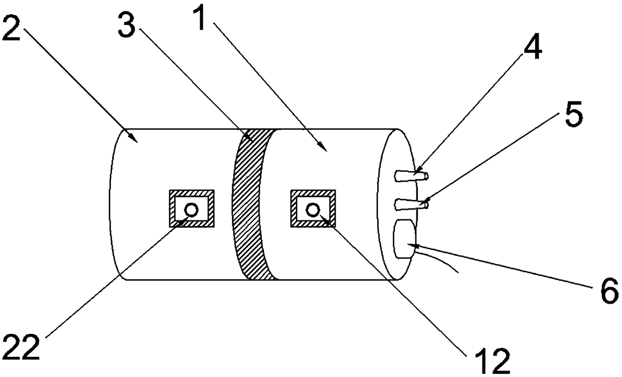
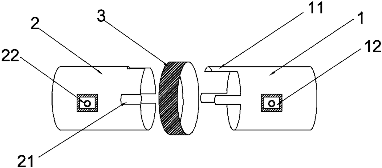
[0019] Embodiment 1 discloses a self-positioning plastic vacuum tank, such as figure 1 As shown, it includes an upper cover 1, a lower cover 2 and a sealing ring 3. The upper cover 1 and the lower cover 2 are sealed and connected by the sealing ring 3. The top of the upper cover 1 of the plastic vacuum tank is also provided with an air inlet 4 and an air outlet 5 respectively. The joints with the pressure sensor 6, the upper cover 1 and the lower cover 2 are respectively provided with self-positioning devices that cooperate with each other, and the sealing ring 3 covers the joints. like figure 2 As shown, the self-positioning device is composed of a protruding plug 11 at the end face of the upper cover 1 and a recessed slot 21 at the end face of the lower cover 2. The size of the plug 11 and the slot 21 are corresponding, and the plug 11 The length does not exceed the width of the sealing ring 3, so that the sealing ring 3 can completely wrap and seal the connection port. I...

Embodiment 2

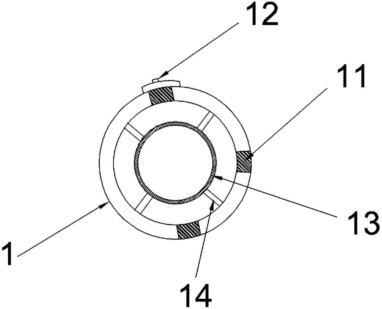
[0021] Embodiment 2 discloses a self-positioning plastic vacuum tank, including an upper cover 1, a lower cover 2 and a sealing ring 3, the upper cover 1 and the lower cover 2 are sealed and connected by the sealing ring 3, and the tank body of the plastic vacuum tank is also provided with There are air inlet holes 4, air outlet holes 5 and pressure sensors 6, and the joints of the upper cover 1 and the lower cover 2 are respectively provided with self-positioning devices that cooperate with each other, and the sealing ring 3 covers the joints. The self-positioning device is composed of a protruding insert 11 at the end face of the upper cover 1 and a recessed slot 21 at the end of the lower cover 2. The size of the insert 11 and the slot 21 are corresponding, and the length of the insert 11 is different. The width of the sealing ring 3 is exceeded, so that the sealing ring 3 can completely wrap and seal the connection port. In this embodiment, there are three inserting blocks...

Embodiment 3

[0023] Embodiment 3 discloses a self-positioning plastic vacuum tank, including an upper cover 1, a lower cover 2 and a sealing ring 3, the upper cover 1 and the lower cover 2 are sealed and connected by the sealing ring 3, and the tank body of the plastic vacuum tank is also provided with There are air inlet holes 4, air outlet holes 5 and pressure sensors 6, and the joints of the upper cover 1 and the lower cover 2 are respectively provided with self-positioning devices that cooperate with each other, and the sealing ring 3 covers the joints. The self-positioning device is composed of a protruding insert 11 at the end face of the upper cover 1 and a recessed slot 21 at the end of the lower cover 2. The size of the insert 11 and the slot 21 are corresponding, and the length of the insert 11 is different. The width of the sealing ring 3 is exceeded, so that the sealing ring 3 can completely wrap and seal the connection port. In this embodiment, there are three inserting blocks...


PUM


Abstract

The invention discloses a self-positioning plastic vacuum tank and belongs to the field of vacuum tanks used for automobile brake vacuum assisting power systems. The self-positioning plastic vacuum tank comprises an upper cover, a lower cover and a sealing ring. The upper cover and the lower cover are in sealed connection through the sealing ring. An air inflow hole, an air outflow hole and a pressure sensor are further arranged on a tank body of the plastic vacuum tank. Self-positioning devices matched with each other are further arranged in the connecting position of the upper cover and thelower cover. The connecting position is coated with the sealing ring. The self-positioning plastic vacuum tank is improved in order to solve the technical problems that an existing iron or stainless steel vacuum tank is complex in machining procedure, low in use quality and easy to corrode and pollute, the rotation angles of an air inflow hole and an air outflow hole of the vacuum tank cannot be controlled, an upper cover and a lower cover are poor in sealing positioning and cannot be aligned, and the parallelism of installation bolts on a tank body is poor. The self-positioning plastic vacuumtank has the beneficial effects that the mass is small, vacuum storage is good, the upper cover and the lower cover can be perfectly aligned and machined, installation is easy, and the tank can be conveniently used and popularized in an automobile enterprise.

Description

technical field [0001] The invention relates to the field of vacuum tanks used in automobile braking systems, in particular to a self-positioning plastic vacuum tank. Background technique [0002] For a long time, fuel vehicles have been the main force in the automotive industry. However, with the increasing environmental pollution and the gradual depletion of oil resources, new energy vehicles have become a new growth point in the auto market. Promoting the transition from high-pollution and high-emission traditional fuel vehicles to zero-emission or low-emission new energy vehicles is the only way for the automotive industry. Traditional fuel vehicles mainly use the rotation of the engine to continuously pump the vacuum to ensure a certain amount of brake power, and the operation method is more sensitive. In existing electric vehicles, the engine has been replaced by an electric motor, and the engine in a hybrid electric vehicle is not always working, and the electric mo...

Claims


Application Information

Patent Timeline
Patent Type & Authority Applications(China)
IPC IPC(8): B60T17/06B60T13/52
CPCB60T13/52B60T17/06
Inventor 邵登马旭王丽张浩周孙进
Owner 芜湖捷欧汽车部件股份有限公司
Why Eureka
Try Eureka